
Semiconductor device testing

Active Publication Date: 2006-03-02
TEXAS INSTR INC
View PDF11 Cites 16 Cited by
  • Summary
  • Abstract
  • Description
  • Claims
  • Application Information

AI Technical Summary

Benefits of technology

[0017] In some other embodiments of the invention, a plurality of CUT couples in parallel between a source pad and a ground pad. The source pad applies a voltage to the CUT and the ground pad provides a ground to the CUT. Each of the CUT is an oscillator. The oscillator further comprises an input coupled to a plurality of inverting logic. A divider couples to one of the plurality of inverting logic. The divider is capable of receiving a signal from one of the plurality of inverting logic and reducing frequency of the signal. An output couples to the divider.
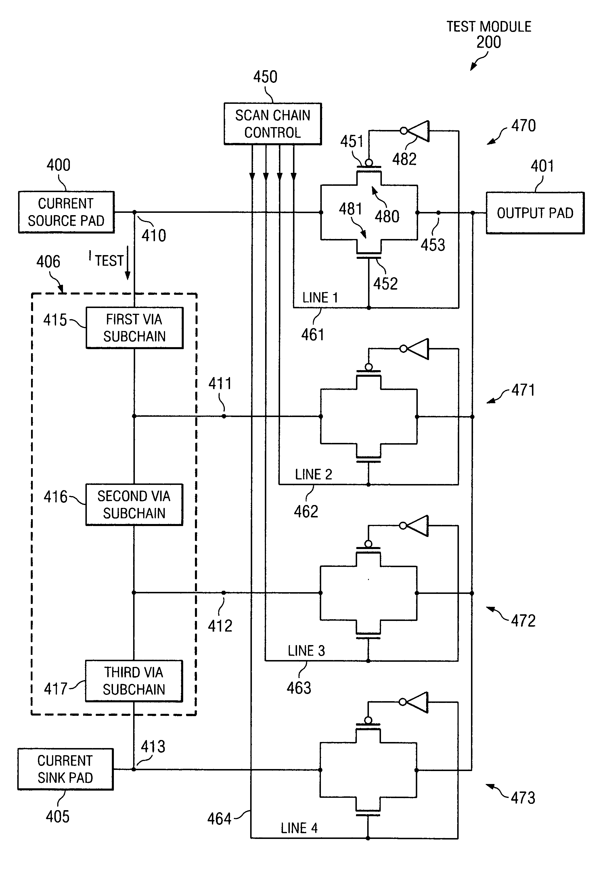
[0018] As described above, a voltage is applied to the CUT and at least one electrical characteristic of the CUT is measured one CUT at a time. A control that may be a scan chain control coupled to each of the plurality of CUT is capable of providing an input signal to test each CUT to determine if the output of each of the CUT matches an expected output for each CUT, thus determining if the CUT are correctly functioning. A multiplexer couples to each CUT. The multiplexer receives an output signal from each CUT. A divider may couple to the multiplexer. The divider may be capable of reducing the frequency of the signal from the multiplexer.

Problems solved by technology

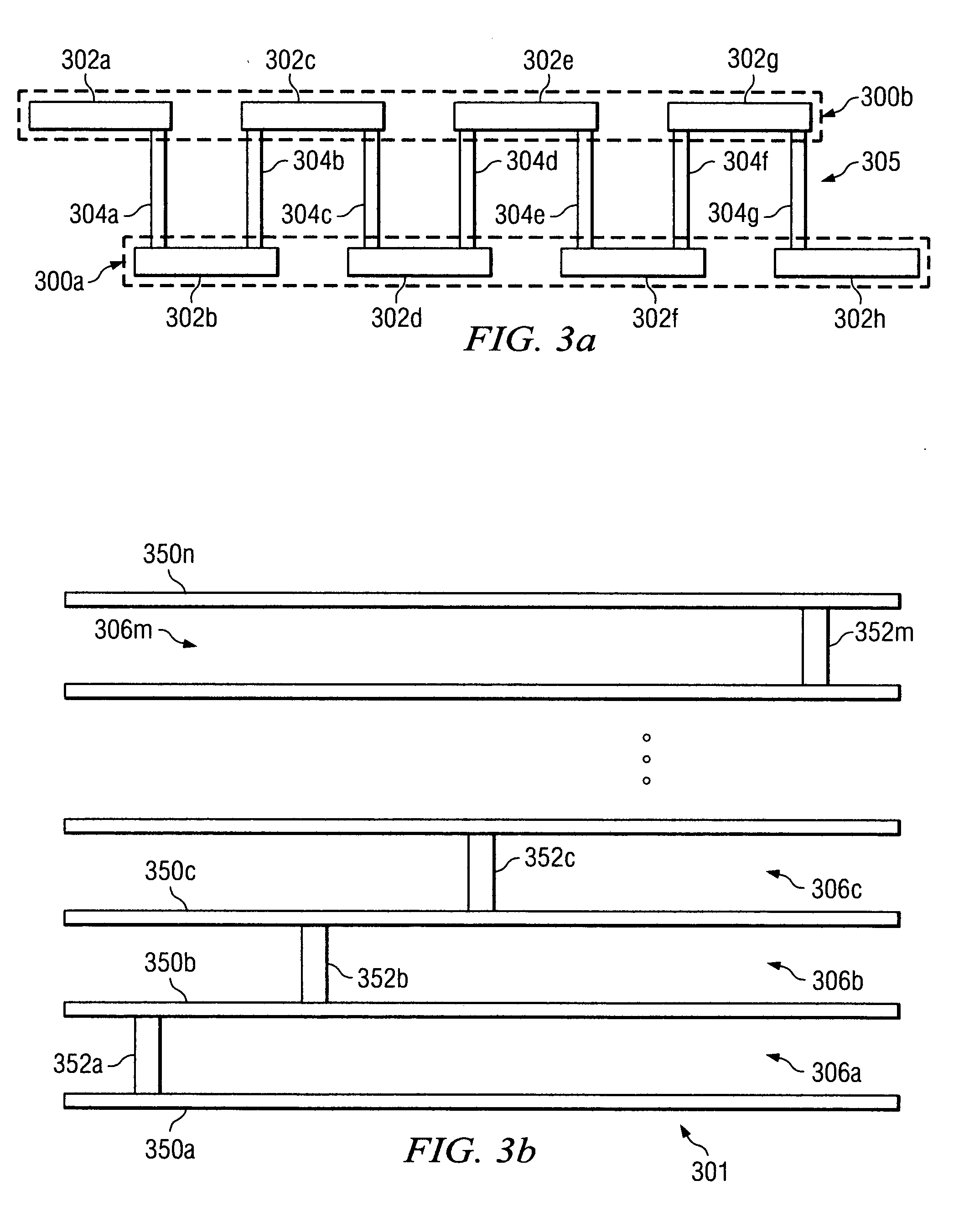
A manufacturing error in one of the components mentioned above may render an IC or semiconductor device incapable of functioning properly.
If a transistor within one of the ICs fails to function properly, the memory device may produce memory errors.
Vias are also subject to manufacturing errors.
When a manufacturing error occurs in a via, the via may not conduct properly and thus may prohibit an IC from functioning correctly.
For instance, an open via or a partially open via may prohibit a device from functioning as designed.
A problem with this approach is that tests may fail to identify via chains containing vias that have slightly larger than expected resistances.
As a result, measuring the resistance of the entire via chain may fail to identify one or more vias with a higher than average resistance in the via chain.
While the test circuitry may test vias and other semiconductor device components so that flawed components may be identified, the test circuitry may take up space on or around the semiconductor device that may otherwise be used to fabricate more IC components.

Method used


Image

  • Semiconductor device testing
  • Semiconductor device testing
  • Semiconductor device testing

Examples


Embodiment Construction

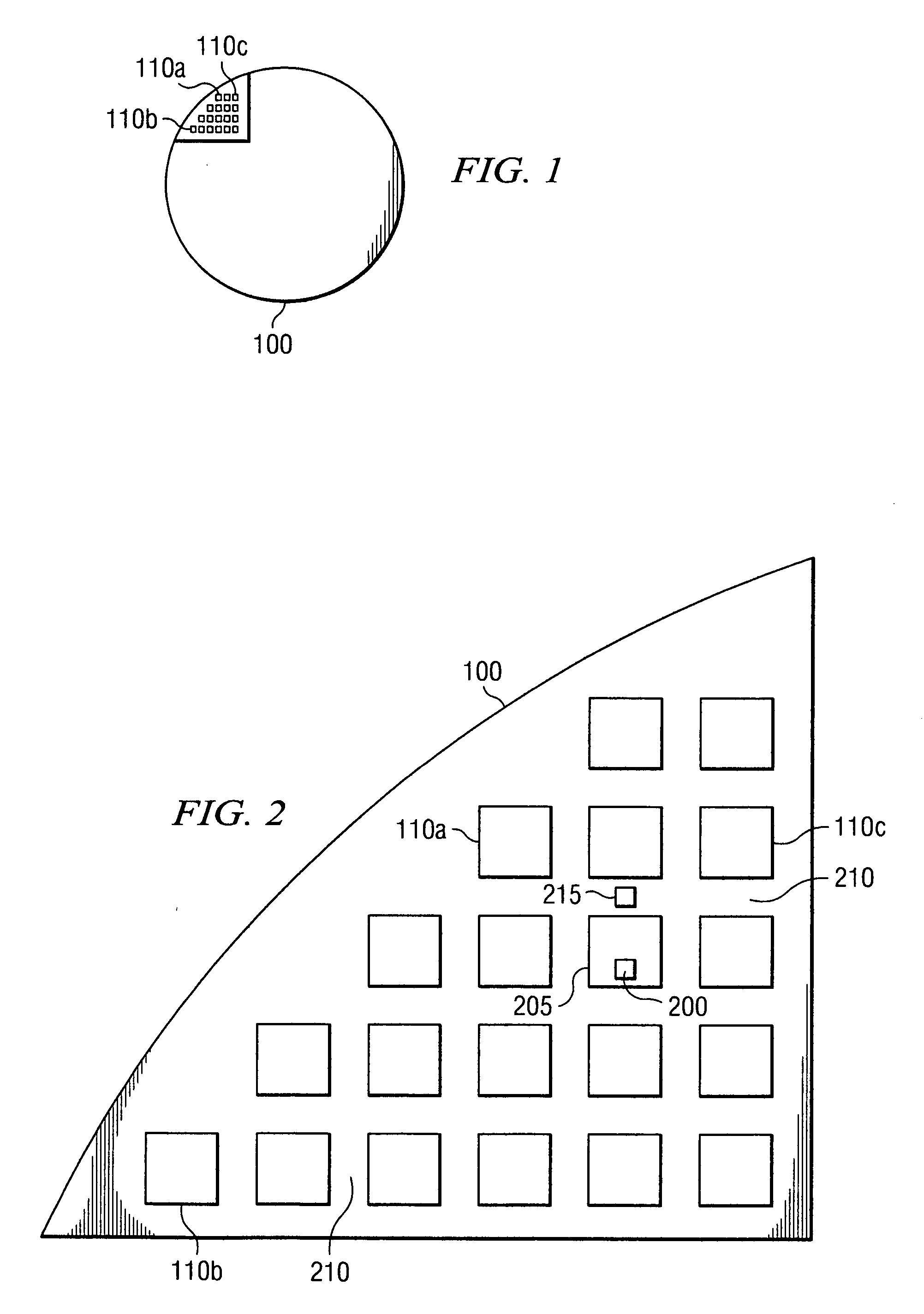
[0032] A semiconductor wafer is a slice of semiconductor material that is divided into small sections known as dies. Semiconductor devices, such as logic gates, are fabricated onto the dies. These devices consist of diodes, transistors, resistors, and capacitors that operate to perform a designed function once the dies are separated from the wafer.

[0033] In a semiconductor wafer, a test module tests vias, transistors, and logic gates, such as oscillators, in semiconductor test structures that are semiconductor devices on a semiconductor die or in a scribe line surrounding the semiconductor die. In some embodiments, the semiconductor test structures may be semiconductor devices fabricated to validate the process for manufacturing integrated circuits. In some other embodiments of the invention, the semiconductor test structure may be semiconductor devices on the die that are part of a functional integrated circuit, such as a digital signal processor (DSP), memory device, transmitter / ...


PUM


Abstract

An apparatus and method to test components in a semiconductor test structure. On a semiconductor wafer, a test module implemented in one or more scribe lines between a plurality of semiconductor dies is used to test components in the semiconductor test structure. The test module may, for example, test electrical characteristics of chains of vias, transistors, and functional devices, such as oscillators. The test module contains a scan chain control coupled through a plurality of pass gates to each component to be tested. The scan chain control sequentially closes the pass gates to separately test the components in the semiconductor test structure. The test module further interfaces with an external testing device and the results of each test are compared with the expected results to identify faulty components.

Description

CROSS REFERENCE TO RELATED APPLICATIONS [0001] This application claims priority under 35 USC §119(e)(1) of Provisional Application No. 60 / 606,600, filed Sep. 2, 2004. [0002] This application is related to the following co-pending application: U.S. patent application Ser. No. __ / ___,___ entitled “APPARATUS AND METHOD FOR TESTING CHAINS OF VIAS AND CONTACTS” filed Sep. 2, 2005, incorporated herein by reference.TECHNICAL FIELD OF THE INVENTION [0003] The present invention generally relates to testing of an electronic device. More particularly, the present invention relates to testing components in a semiconductor device. Still more particularly, the present invention relates to using active devices to test components in a semiconductor device. BACKGROUND OF THE INVENTION [0004] An integrated circuit (IC) is a semiconductor device containing many small, interconnected components such as diodes, transistors, resistors, and capacitors. These components function together to enable the IC t...

Claims


Application Information

Patent Timeline
IPC IPC(8): G01R31/26
CPCG01R31/31723G01R31/318572G01R31/318558G01R31/318511
Inventor CANO, FRANCISCOMARTINEZ, JUAN C.
Owner TEXAS INSTR INC
Learn More