Secondary protective element for secondary battery

a secondary battery and protective element technology, applied in the field of secondary protective elements for secondary batteries, can solve the problems of sudden rise in voltage, damage to functional elements, and difficulty in bending lead plates in a position away from functional elements by a predetermined distance, so as to prevent the characteristics of secondary protective elements from being degraded

Inactive Publication Date: 2006-03-02
SAMSUNG SDI CO LTD
View PDF7 Cites 39 Cited by
  • Summary
  • Abstract
  • Description
  • Claims
  • Application Information

AI Technical Summary

Benefits of technology

[0013] Accordingly, the present invention has been made to solve one or more of the above-mentioned problems occurring in the prior art, and the claimed invention is directed to providing a secondary protective element for a secondary battery, in which a lead plate of the secondary protective element is formed at a predetermined portion thereof with a bending section so that the bending section of the lead plate is bent when the secondary protective element is mounted on a secondary battery pack, thereby preventing characteristics of the secondary protective element from being degraded.

Problems solved by technology

However, in such a lithium secondary battery, voltage can suddenly rise if an internal short circuit, an external short circuit or overcharge / over-discharge of an electrode assembly occurs in the lithium secondary battery.
In more detail, if the bending section of the lead plate is closely adjacent to the functional element, stress is applied to the functional element, so the characteristics of the functional element can vary or the functional element can be damaged.
However, if the secondary battery pack is includes the secondary protective element, bending the lead plate and mounting of the secondary protective element must be performed within a narrow space, such that it is very difficult to bent the lead plate in a position away from the functional element by a predetermined distance.

Method used


Image

  • Secondary protective element for secondary battery
  • Secondary protective element for secondary battery
  • Secondary protective element for secondary battery

Examples


first embodiment

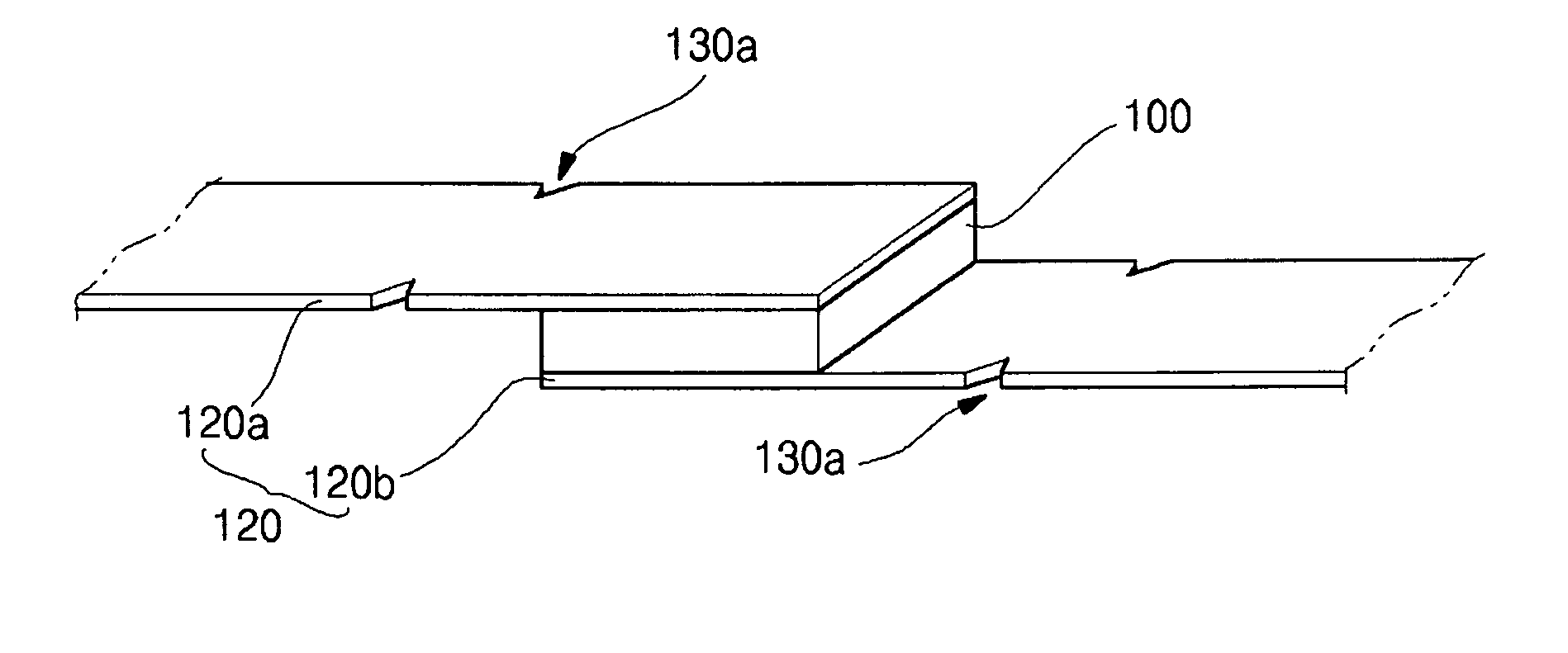
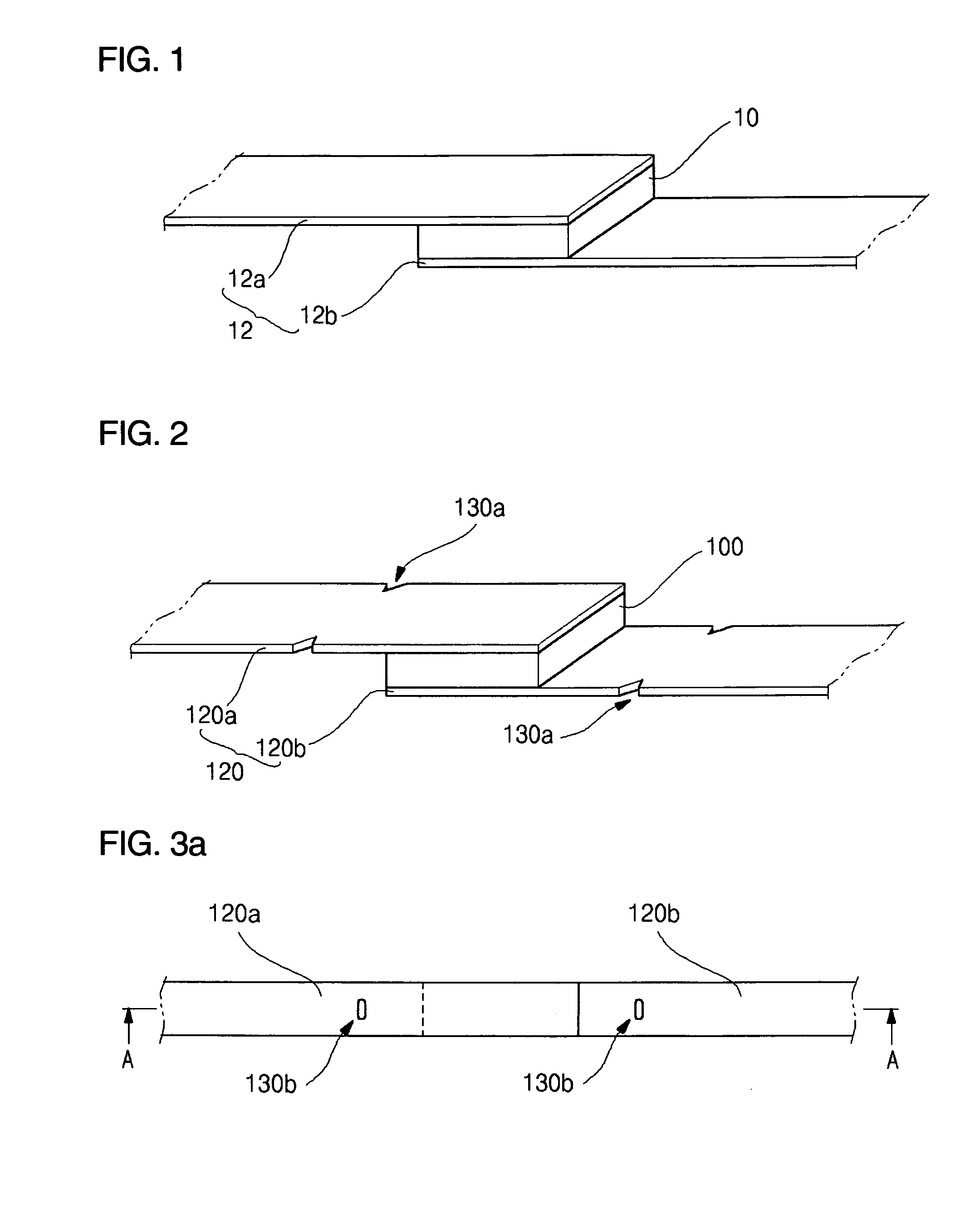
[0047] According to the present invention, as shown in FIG. 2, the lead plate 120 includes a bending section 130a formed at a predetermined portion of the lead plate 120 while being spaced from the functional element 100. The bending section 130a guides the bending position of the lead plate 120 in such a manner that the lead plate 120 can be bent about the bending section 130a. Preferably, the bending section 130a is spaced from the functional element 100 by at least 2 mm. If the distance between the bending section 130a and the function element 10 is shorter than 3 mm, the characteristics of the functional device 100 can be degraded while bending the lead plate 120.

[0048] The bending section 130 can be formed on at least one of the first lead plate 120a and the second lead plate 120b according to the shape of the secondary battery pack on which the secondary protective element is mounted. The bending section 130a can be formed with various shapes and sizes. Since the lead plate 12...

second embodiment

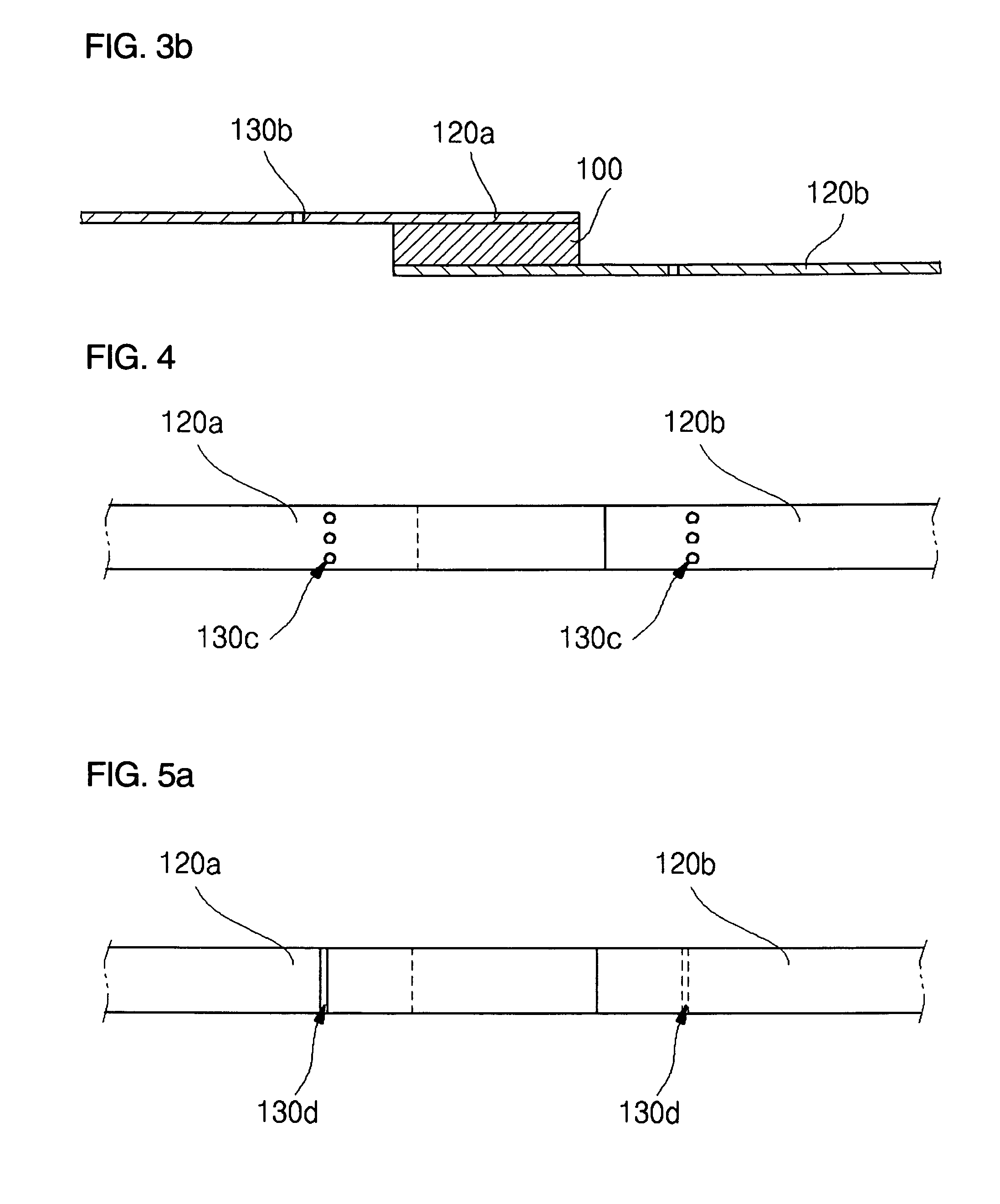
[0050] According to the present invention as shown in FIGS. 3a and 3b, a bending section 130b including an elongated aperture having a predetermined width and a predetermined length is formed in bending positions of the lead plate 120. The bending section 130b can be formed with various shapes, such as a square or oval shape, a rectangular shape, or a lozenge shape. The present invention does not limit the shape of the bending section 130b. In addition, since the bending section 130b guides the lead plate 120 such that a predetermined portion of the lead plate 120 can be bent, the bending section 130b is formed with a predetermined size sufficient for bending the lead plate 120. Preferably, a width of the bending section 130b is within 1.0 mm, and a length of the bending section 130b is within 50% of a width of the lead plate 120 so as to prevent the lead plate 120 from weakening, thereby preventing the lead plate 120 from being broken during bending or following processes.

third embodiment

[0051] According to the present invention, as shown in FIG. 4, bending sections 130c including at least two apertures are formed widthwise along the lead plate 120 while forming a predetermined interval therebetween. Preferably, a diameter or a width of the bending section 130c is within 1.0 mm so as to so as to prevent the lead plate 120 from weakening, thereby preventing the lead plate 120 from being broken during bending or following processes.

[0052] It is also possible to provide the bending section by combining the bending sections of FIGS. 2 and 3a or the bending sections of FIGS. 2 and 4.


PUM

PropertyMeasurementUnit
distanceaaaaaaaaaa
lengthaaaaaaaaaa
thicknessaaaaaaaaaa

Abstract

A secondary protective element includes: a functional element; a lead plate arranged on least one of upper and lower surfaces of the functional element; and at least one bending section arranged on a predetermined portion of the lead plate.

Description

CLAIM OF PRIORITY [0001] This application makes reference to, incorporates the same herein, and claims all benefits accruing under 35 U.S.C. §119 from an application entitled SECONDARY PROTECTIVE ELEMENT FOR SECONDARY BATTERY, earlier filed in the Korean Intellectual Property Office on 28 Jul. 2004 and there duly assigned Serial No. 10-2004-0059430. BACKGROUND OF THE INVENTION [0002] 1. Field of the Invention [0003] The present invention relates to a secondary protective element for a secondary battery, and more particularly to a secondary protective element for a secondary battery, in which a predetermined portion of lead plate of the secondary protective element includes a bending section which is bent when the secondary protective element is mounted on a secondary battery pack, thereby preventing the characteristics of the secondary protective element from being degraded. [0004] 2. Description of the Related Art [0005] As generally known in the art, portable wireless appliances, ...

Claims


Application Information

Patent Timeline
Patent Type & Authority Applications(United States)
IPC IPC(8): H02H5/04H01M50/583
CPCH01M2/34H01M2200/106H01M2/348Y02E60/10H01M50/581H01M50/583H01M50/572
Inventor KIM, JUN-HOKIM, CHAN-JUNG
Owner SAMSUNG SDI CO LTD
Why Eureka
Try Eureka