Lamp for vehicle

a technology for vehicles and lamps, applied in the direction of semiconductor devices for light sources, fixed installations, lighting and heating apparatus, etc., can solve the problems of large interior space occupied by lamps, large time and cost, and inability to meet the desired illuminance distribution

Inactive Publication Date: 2006-03-02
TECHSIGN
View PDF6 Cites 55 Cited by
  • Summary
  • Abstract
  • Description
  • Claims
  • Application Information

AI Technical Summary

Benefits of technology

[0034] According to the present invention, the lamp can be used as a lamp capable of emitting light having a plurality of colors using a single light guide panel by installing the light-transmitting filters having various colors between the plurality of light sources and the light guide panel. In addition, when the plurality of stacked light guide panels are used, it is possible to a compact lamp capable of emitting light having a variety of colors by installing the filters with desired colors between the light sources and the light guide panels, respectively, so that respective layers can represent different colors.

Problems solved by technology

In the conventional lamp for a vehicle, however, if the shape of the lamp is modified according to changes in the design of the vehicle, here is a problem in that a lot of time and costs are required for designing and manufacturing a lamp satisfying desired illuminance distribution.
This is because to performance of the lamp depends on the shape of the reflector or lens and thus an external appearance of the lamp cannot be arbitrarily modified, thereby requiring a lot of time and costs in modifying the shape of the reflector or lens.
Accordingly, there is a disadvantage in that the lamp occupies a larger interior space in the vehicle.
In addition, since the conventional lamp achieves illumination using light emitted from a single point light source installed in the vicinity of a focal length of the reflector, there are problems in that peripheral components may be thermally deformed due to heat generated from the concentrated light source, or moisture may be condensed within the lamp due to a large temperature difference between the interior and exterior of the lamp.

Method used


Image

  • Lamp for vehicle
  • Lamp for vehicle
  • Lamp for vehicle

Examples


Embodiment Construction

[0054] Hereinafter, preferred embodiments of the present invention will be described in detail with reference to accompanying drawings.

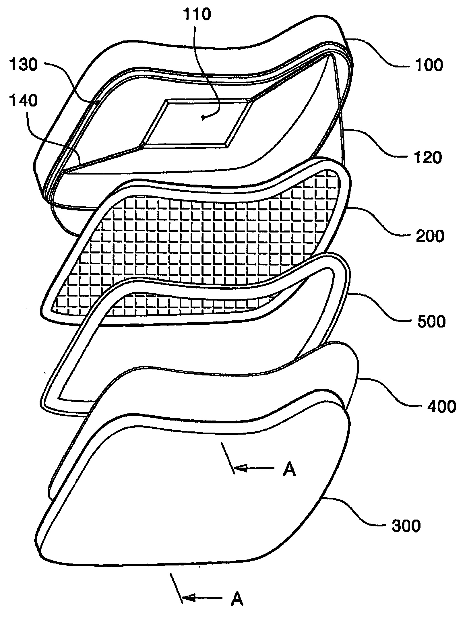
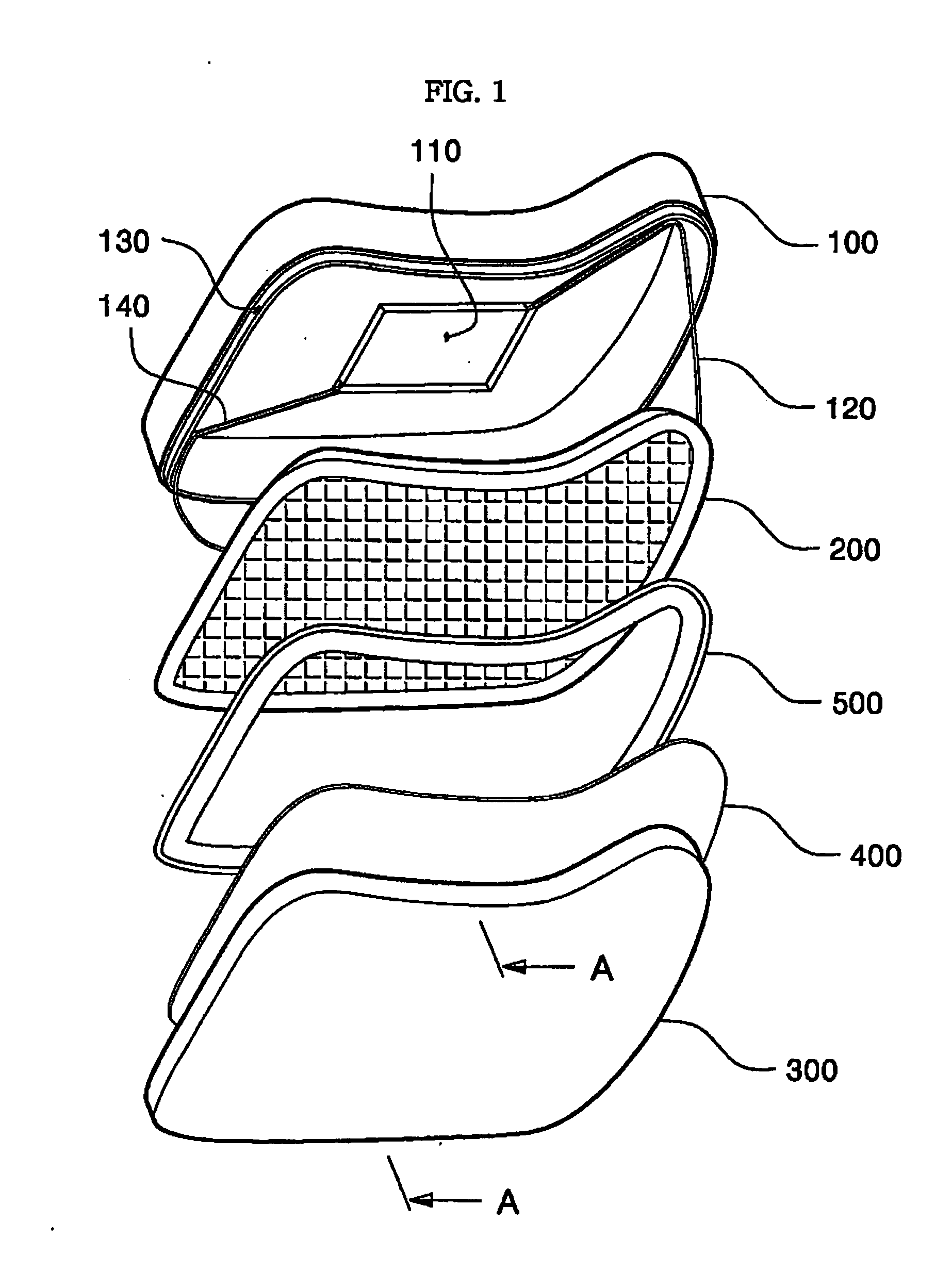
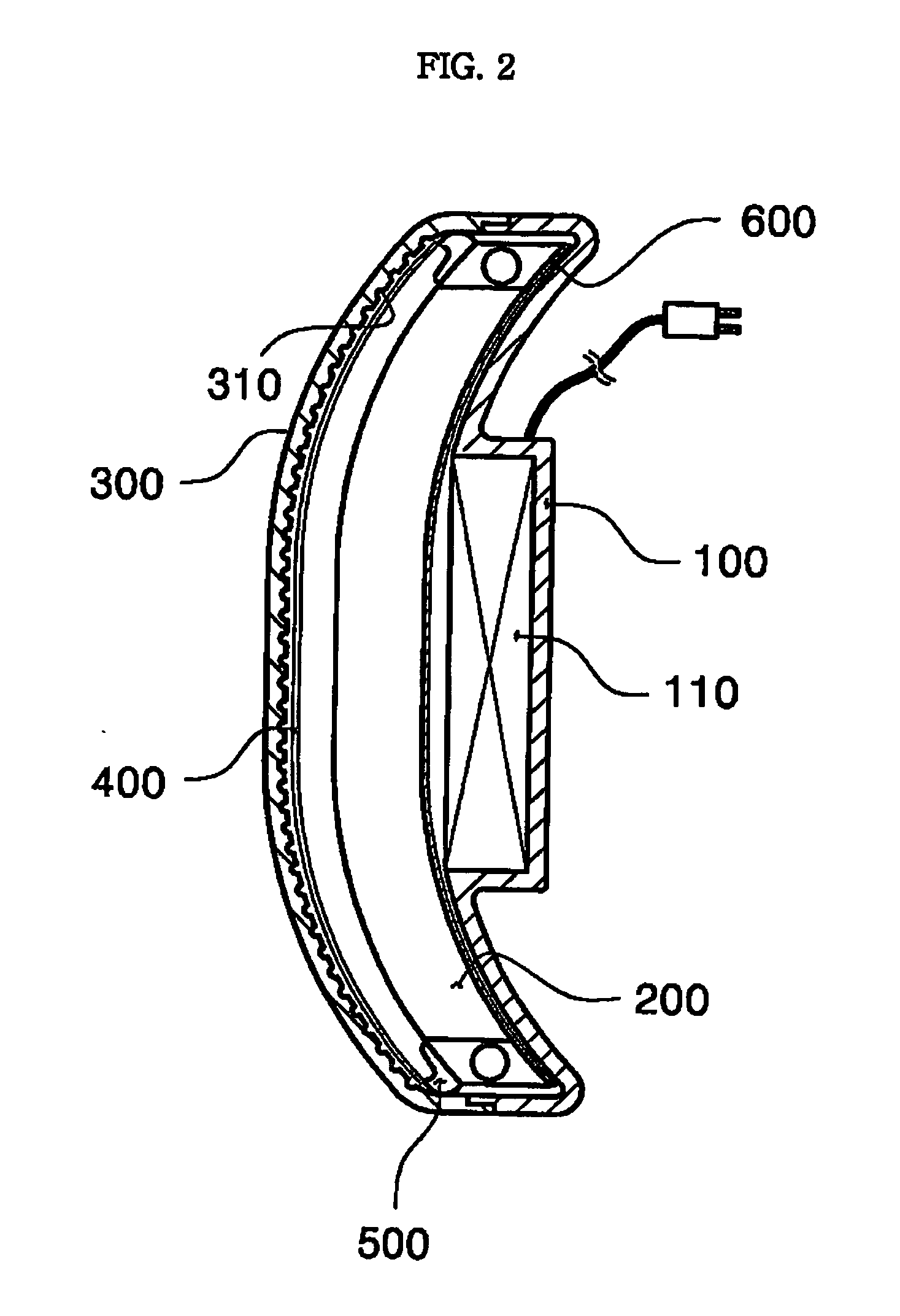
[0055]FIG. 17 schematically illustrates an operating principle of a lamp for a vehicle according to the present invention. Light emitted from a light source 230 is incident into a light guide panel 210 through a side surface (light incidence plane) of the light guide panel. The light that travels while being subjected to total reflection within the light guide panel 210 is scattered by a scattering pattern formed on a rear surface of the light guide panel and then exits through a front surface of the light guide panel (light exit plane). The light that exits through the front surface of the light guide panel 210 is irradiated forward with an appropriate pattern through a cover member 300 with a lens pattern formed therein. That is, compared with a conventional lamp for a vehicle as shown in FIG. 18, the lamp using the light guide panel has advantage...


PUM


Abstract

The present invention relates to a lamp for a vehicle, wherein light is caused to be incident into a light guide panel from a side surface of the plate-shaped light guide panel, the light is propagated within the light guide panel by means of total reflection and scattered by a scattering pattern formed on a rear surface of the light guide panel so that the light can be radiated to a front surface of the light guide panel, and the light radiated to the front surface is then radiated forward with a predetermined pattern by means of a cover member provided with a lens pattern. A lamp for a vehicle according to the present invention comprises a housing having an opening through which light radiates; a light-transmitting cover member which has a light incidence plane and a light exit plane, and is fixedly installed on the housing to hermetically cover the opening of the housing and provided with a lens pattern formed on the light incidence plane and/or the light exit plane; a plate-shaped light guide panel which has a light incidence plane defined at a side surface thereof to receive light and a light exit plane defined at a front surface thereof to face the cover member and is provided with a scattering pattern for scattering light incident on the light incidence plane thereof toward the light exit plane thereof; a light source installed at a portion adjacent to the light incidence plane of the light guide panel to emit the light to the light incidence plane; and a reflection plate installed on a rear surface of the light guide panel to reflect the light toward a front surface of the light guide panel.

Description

TECHNICAL FIELD [0001] The present invention relates to a lamp for a vehicle having a light guide panel, which can be used for a headlamp, a fog lamp, a back-up lamp, a clearance lamp, a lamp for illuminating a number plate, a tail lamp, a brake lamp, a turn signal lamp and an emergency flickering lamp mounted to the exterior of a vehicle, or an indoor lamp mounted to the interior of the vehicle. More particularly, the present invention relates to a lamp for a vehicle, wherein light is caused to be incident into a light guide panel from a side surface of the plate-shaped light guide panel, the light is propagated within the light guide panel by means of total reflection and scattered by a scattering pattern formed on a rear surface of the light guide panel so that the light can be radiated to a front surface of the light guide panel, and the light radiated to the front surface is then radiated forward with a predetermined pattern by means of a cover member provided with a lens patte...

Claims


Application Information

Patent Timeline
Patent Type & Authority Applications(United States)
IPC IPC(8): F21V7/04B60Q1/00F21S8/10F21S8/12F21Y101/00
CPCB60Q1/0058B60Q1/2607B60Q2400/20F21S48/1241F21Y2101/02F21S48/2243F21S48/2268F21S48/2281F21S48/2237F21Y2115/10F21S41/24F21S43/237F21S43/239F21S43/245F21S43/249B60Q1/00
Inventor SA, JONG-YUB
Owner TECHSIGN
Why Eureka
Try Eureka