
Method and system for reducing the peak current in refreshing dynamic random access memory devices

Inactive Publication Date: 2006-03-02
ROUND ROCK RES LLC
View PDF8 Cites 105 Cited by
  • Summary
  • Abstract
  • Description
  • Claims
  • Application Information

AI Technical Summary

Benefits of technology

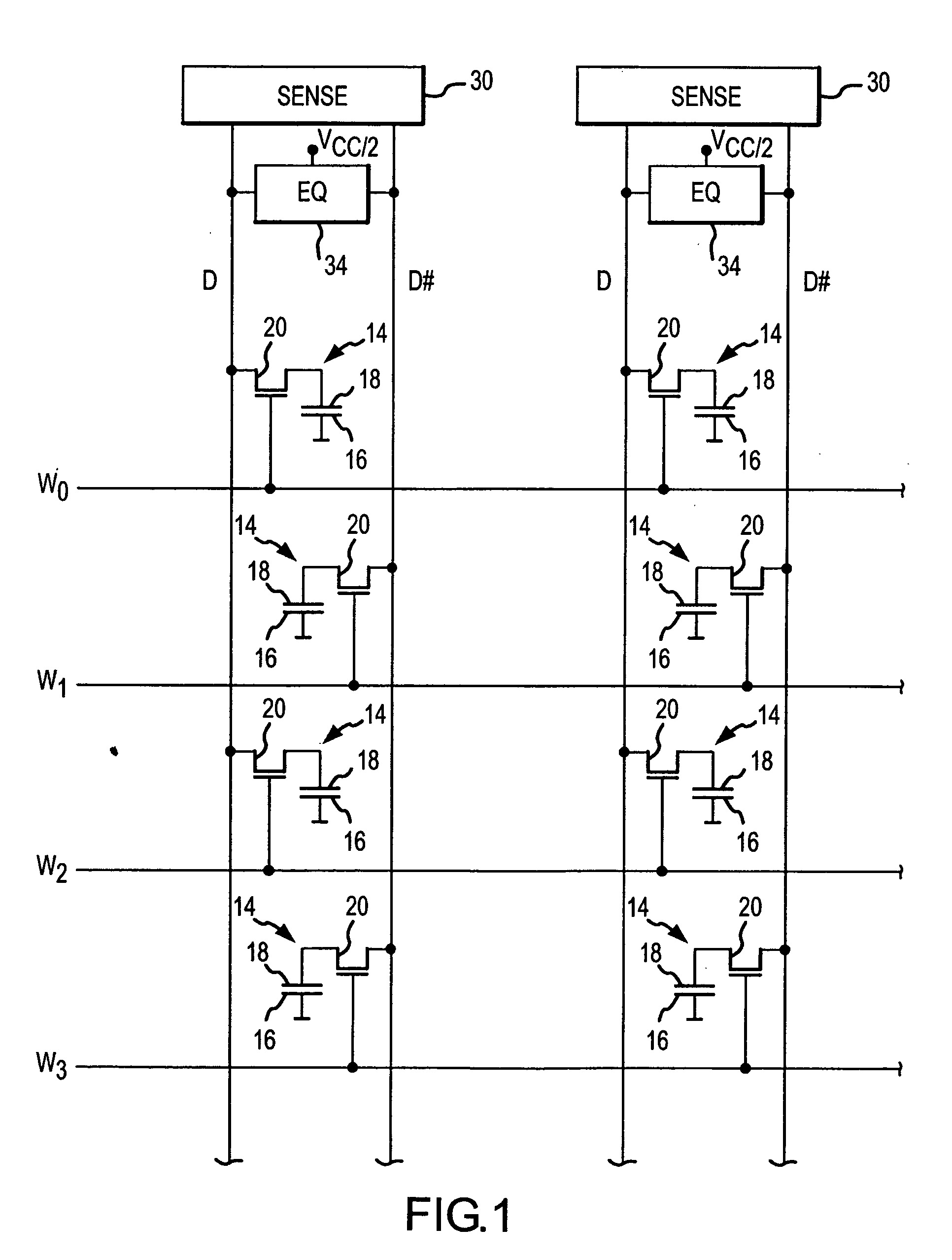
[0015] A plurality of DRAM devices in a memory system are each configured with a delay value. When a refresh command is issued simultaneously to the DRAM devices, the DRAM devices initiate refreshes of their memory cells at different times corresponding to their respective delay values. As a result, the current drawn by the DRAM devices in conducting the refreshes are spread over the period during which the DRAM devices are initiating the refreshes, thereby limiting the peak current consumption of the DRAM devices in the memory system. The DRAM devices may be configured by storing a delay value corresponding to a number of system clock signal periods and / or fraction thereof. The DRAM devices will then delay initiating a refresh in response to a refresh command until after the clock periods corresponding to the delay value.

Problems solved by technology

As a result, the current drawn by the DRAM devices in conducting the refreshes are spread over the period during which the DRAM devices are initiating the refreshes, thereby limiting the peak current consumption of the DRAM devices in the memory system.

Method used


Image

  • Method and system for reducing the peak current in refreshing dynamic random access memory devices
  • Method and system for reducing the peak current in refreshing dynamic random access memory devices
  • Method and system for reducing the peak current in refreshing dynamic random access memory devices

Examples


Embodiment Construction

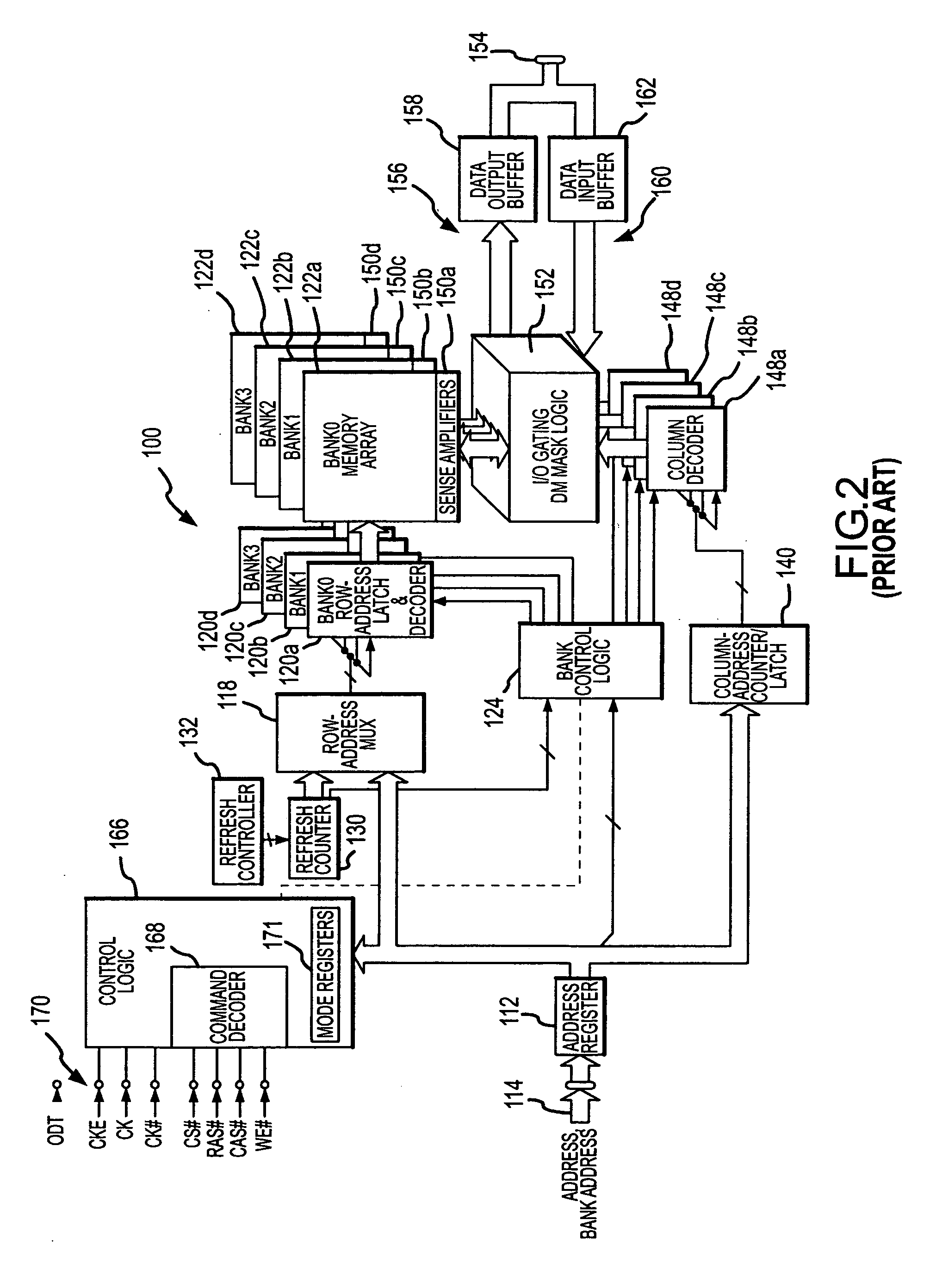
[0025] A typical synchronous dynamic random access memory (“SDRAM”) device 100 that can use various embodiments of the present invention described below is shown in FIG. 2. The SDRAM 100 includes an address register 112 that receives either a row address or a column address on an address bus 114. The address bus 114 is generally coupled to a memory controller (not shown in FIG. 2). Typically, a row address is initially received by the address register 112 and applied to a row address multiplexer 118. The row address multiplexer 118 couples the row address to row address latches and decoder 120a-d, which are, in turn, coupled to respective banks 122a-d of DRAM memory cell arrays. The row address latches and decoders 120a-d stores the row address and decodes the stored address to apply row actuating signals to the memory cells in the respective banks. The row address multiplexer 118 also couples row addresses to the row address latches and decoders 120a-d for the purpose of refreshing...


PUM


Abstract

A dynamic random access memory device includes a mode register that is programmed with a delay value. In some embodiments, a offset code is also stored in the memory device. The memory device uses the delay value, which may be added to or multiplied by the offset code, to delay the initiation of a received auto-refresh or self-refresh command. A large number of dynamic random access memory devices in a system may be provided with different delay values and possibly offset codes so that the memory device do not all perform refreshes simultaneously in response to an auto-refresh or self-refresh command issued to all of the memory devices simultaneously. As a result, the peak current drawn by the memory devices resulting from the auto-refresh command or self-refresh command is maintained at a relatively low value.

Description

FIELD OF THE INVENTION [0001] The present invention relates to memory systems, and more particularly, to systems and methods for reducing the peak current demand of dynamic random access memory devices when memory cells are to be refreshed. BACKGROUND OF THE INVENTION [0002] A variety of memory devices are in common use in a wide range of electronic devices. A common variety of memory devices are dynamic random access memory (“DRAM”) devices, which are used in a variety of applications, such as for system memory in computer systems. As is well known in the art, a DRAM device includes a large number of DRAM memory cells that are essentially individual capacitors that store one of two voltage levels corresponding to respective binary values of a data bit. As also well known in the art, capacitors, including those used as DRAM memory cells, leak charge and therefore cannot retain a voltage level indefinitely. For this reason, it is necessary to periodically restore the voltage initiall...

Claims


Application Information

Patent Timeline
IPC IPC(8): G11C7/00
CPCG11C11/406G11C11/40611G11C11/40622G11C11/40618G11C11/40615
Inventor KINSLEY, THOMAS H.JANZEN, JEFFERY W.
Owner ROUND ROCK RES LLC
Learn More