Insert molding apparatus and insert molding method
- Summary
- Abstract
- Description
- Claims
- Application Information
AI Technical Summary
Benefits of technology
Problems solved by technology
Method used
Image

Examples
first embodiment
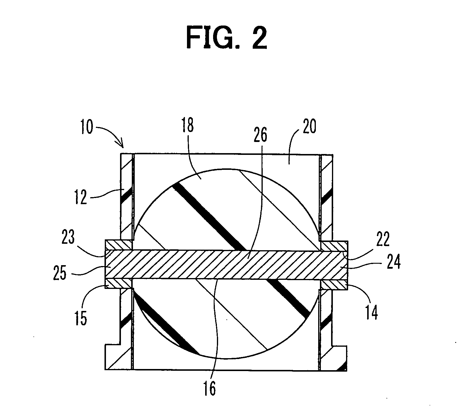
[0058] A first embodiment of the present invention will be described with reference to FIGS. 1 to 7. FIG. 2 shows a throttle device 10, which serves as an insert molded product that is molded according to a first embodiment of the present invention. The throttle device 10 is installed in a vehicle to control an intake air flow rate of an internal combustion engine.
[0059] The throttle device 10 includes a body 12, bearings (serving as first type insert elements) 14, 15, a shaft (serving as a second type insert element) 16 and a valve body 18. The body 12 is formed into a cylindrical tubular body made of a resin material, and an air intake passage 20 is formed in the body 12. The bearings 14, 15 are embedded in the body 12 in the following manner. That is, the air intake passage 20 is located between the bearings 14, 15, so that the bearings 14, 15 oppose each other in a radial direction of the air intake passage 20. The bearings 14, 15 have the same shape and are coaxially arranged....
second embodiment
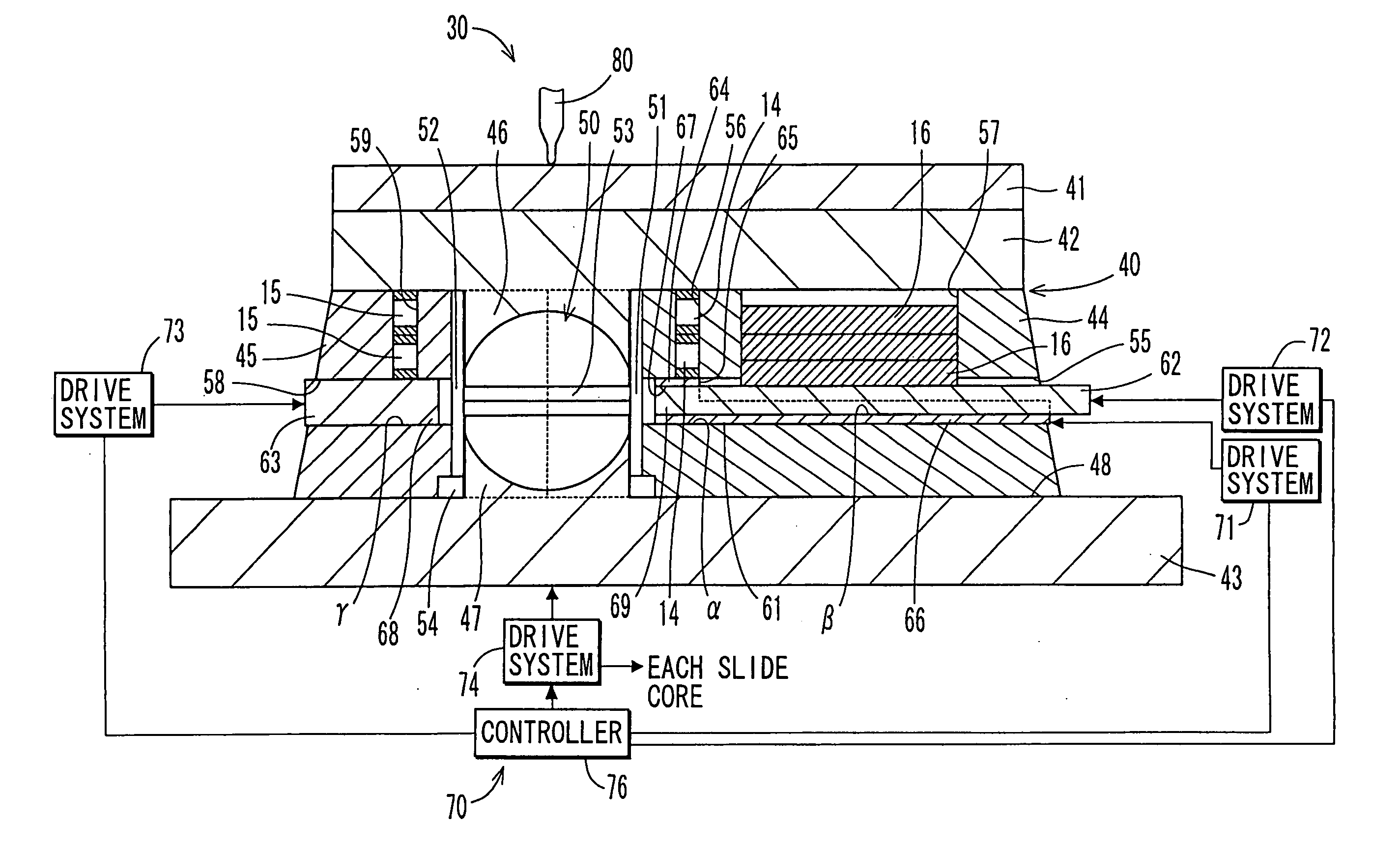
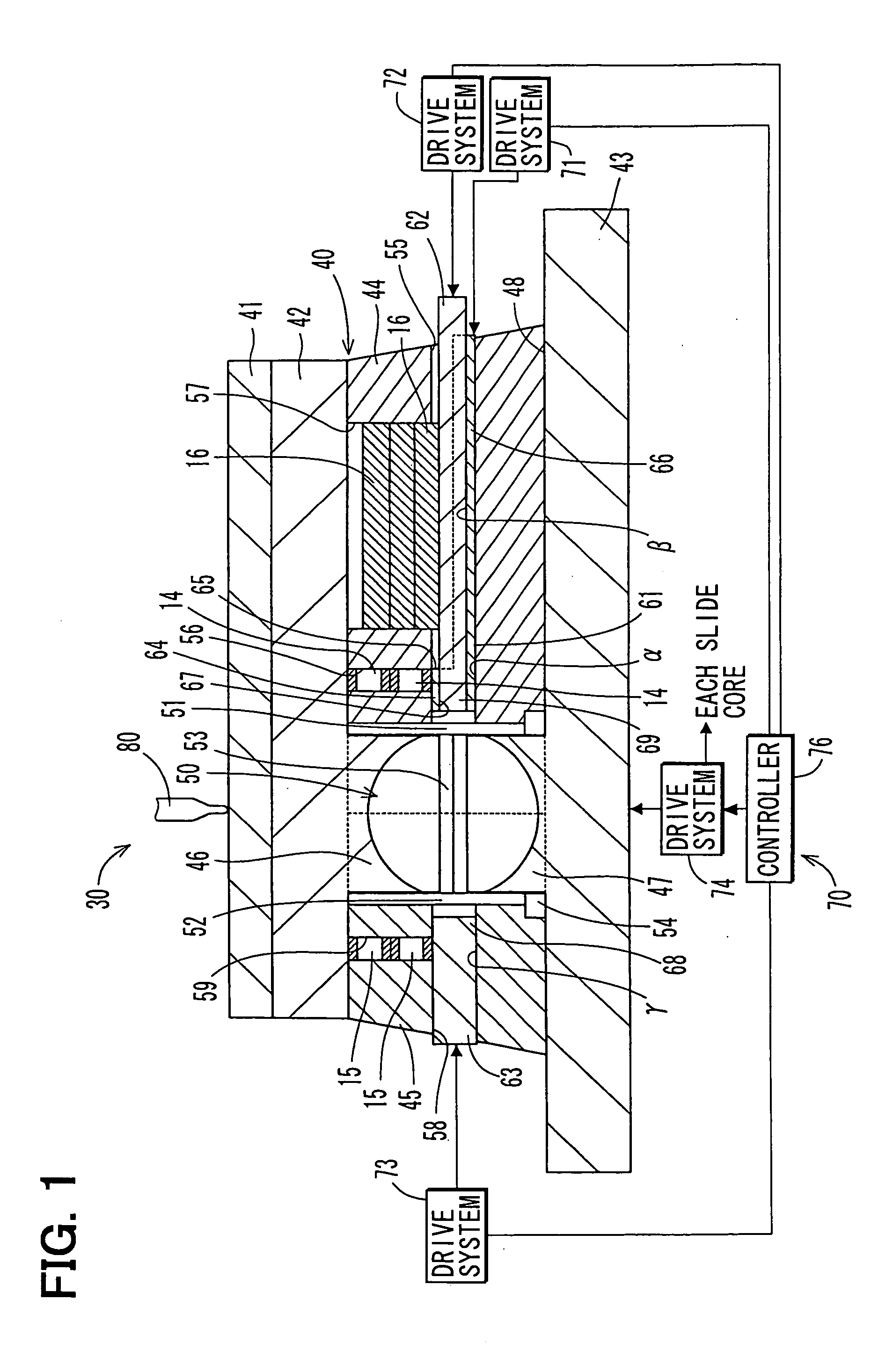
[0093] A second embodiment of the present invention is a modification of the first embodiment, and FIGS. 8-10 show the insert molding apparatus 100 of the second embodiment. Hereinafter, components similar to those of the first embodiment are indicated by the same numeral and will not be described further for the sake of simplicity.
[0094] In the insert molding apparatus 100, a recess 122 is provided in the distal end portion 121 of the second pusher 120. The recess 122 is engageable with a protrusion 110, which is provided in the journal portion 24 of the shaft 16. The protrusion 110 has a double sided structure, which includes two planar outer surfaces 113, 114, which are parallel to each other and are diametrically opposed to each other in the journal portion 24. The recess 122 is formed into a complementary shape, which is complementary to the protrusion 110 and includes two planar inner surfaces 123, 124, which are parallel to each other and are diametrically opposed to each ot...
third embodiment
[0101] A third embodiment of the present invention is a modification of the second embodiment, and FIGS. 11-13 show the insert molding apparatus 150 of the third embodiment. Hereinafter, components similar to those of the second embodiment are indicated by the same numeral and will not be described further for the sake of simplicity.
[0102] In the insert molding apparatus 150, the third pusher 160 is not formed as the cylindrical solid bar. Rather, the third pusher 160 of the third embodiment is formed as a cylindrical tube, which has an inner diameter that allows coaxial insertion of a guide pusher 170 into the third pusher 160.
[0103] The guide pusher 170 is formed as a metal cylindrical solid bar, which extends linearly in the axial direction. In the section of the guide pusher 170 other than a distal end portion 171 of the guide pusher 170, an outer diameter of the guide pusher 170 is generally the same as the inner diameter of the first and third pushers 61, 160 and the inner d...
PUM
| Property | Measurement | Unit |
|---|---|---|
| Force | aaaaa | aaaaa |
| Diameter | aaaaa | aaaaa |
Abstract
Description
Claims
Application Information
 - R&D Engineer
- R&D Manager
- IP Professional
- Industry Leading Data Capabilities
- Powerful AI technology
- Patent DNA Extraction
Browse by: Latest US Patents, China's latest patents, Technical Efficacy Thesaurus, Application Domain, Technology Topic.
© 2024 PatSnap. All rights reserved.Legal|Privacy policy|Modern Slavery Act Transparency Statement|Sitemap