System for fuel cell power plant load following and power regulation

a technology of load following and power regulation, which is applied in the direction of electrochemical generators, process and machine control, instruments, etc., can solve the problems of shortening the service life of the fuel cell power plant, reducing the performance of the fuel cell, and affecting the service life of the fuel cell. achieve the effect of constant chemical reaction rate of the fuel cell

Inactive Publication Date: 2006-03-02
CATERPILLAR INC
View PDF15 Cites 37 Cited by
  • Summary
  • Abstract
  • Description
  • Claims
  • Application Information

AI Technical Summary

Benefits of technology

[0008] In another embodiment, a system is provided for controlling a fuel cell power plant system. The system includes a fuel cell providing electric power and a load bank for dissipating power from the fuel cell. The system may also include an inverter controller for adjusting the load operations of the load bank based on detected changes to an external load receiving power from the fuel cell power plant and a fuel cell controller for maintaining a constant chemical reaction rate of the fuel cell despite load changes to the external load.

Problems solved by technology

Thus, an unbalanced condition can exist within the fuel cell.
The unbalanced condition may shorten the service life of the fuel cell power plant and may also reduce its performance as well.
This again will cause the unbalanced condition and, therefore, affect the performance of the fuel cell power plant.
The power plant then has to go through a “dwell” cycle, which limits the availability of the plant for a period up to 10 hours before the power plant can provide power to the grid again.
The unbalanced condition between the external load change and the fuel cell chemical reaction rate happens more frequently in grid-disconnected mode than in grid-connected mode.
Some fuel cell technologies do not exhibit the unbalanced conditions due to faster reaction times. However, these methods and systems generally increase the complexity and cost of the fuel cell power plant and its management systems.

Method used


Image

  • System for fuel cell power plant load following and power regulation
  • System for fuel cell power plant load following and power regulation
  • System for fuel cell power plant load following and power regulation

Examples


Embodiment Construction

[0014] Reference will now be made in detail to the exemplary aspects of the invention, examples of which are illustrated in the accompanying drawings. Wherever possible, the same reference numbers will be used throughout the drawings to refer to the same or like parts.

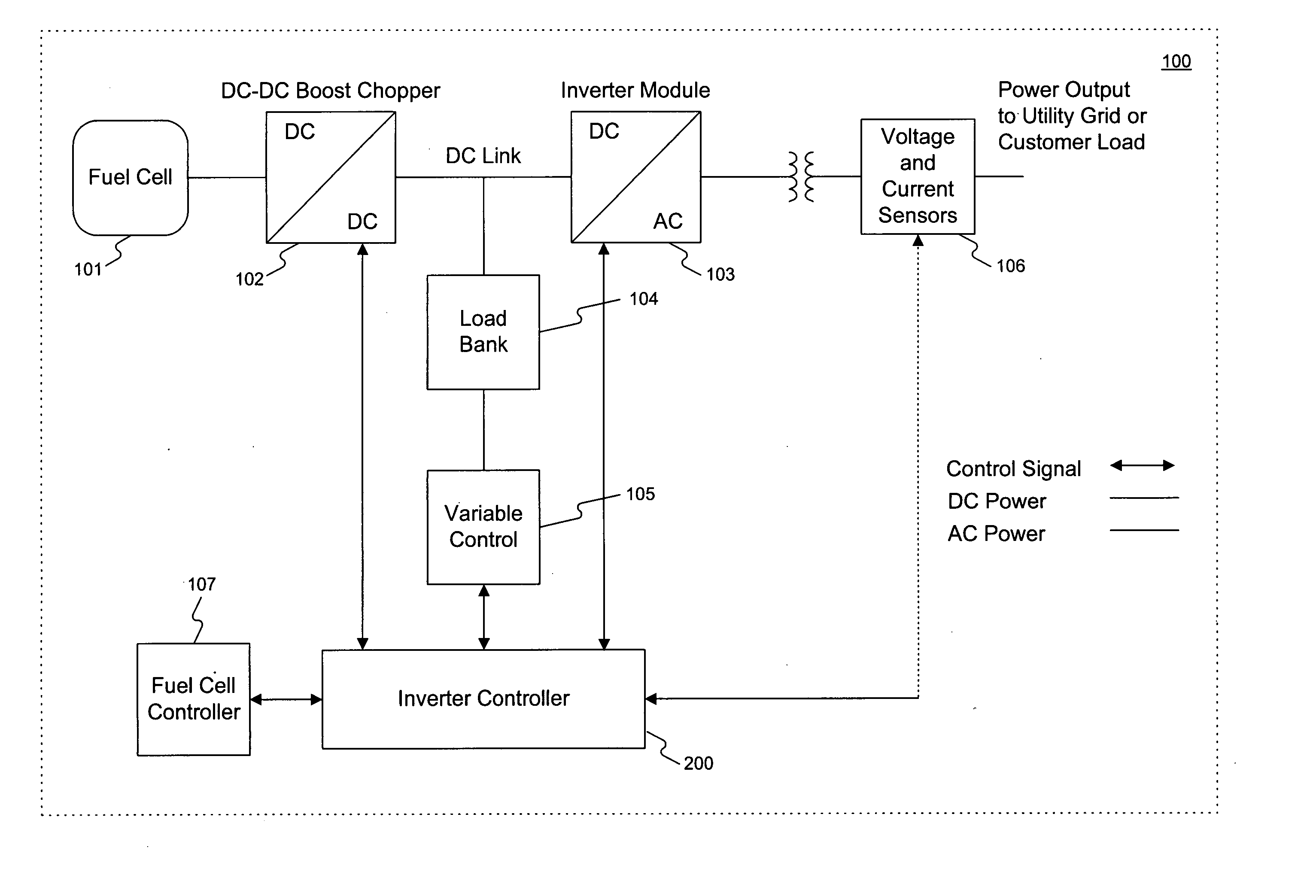
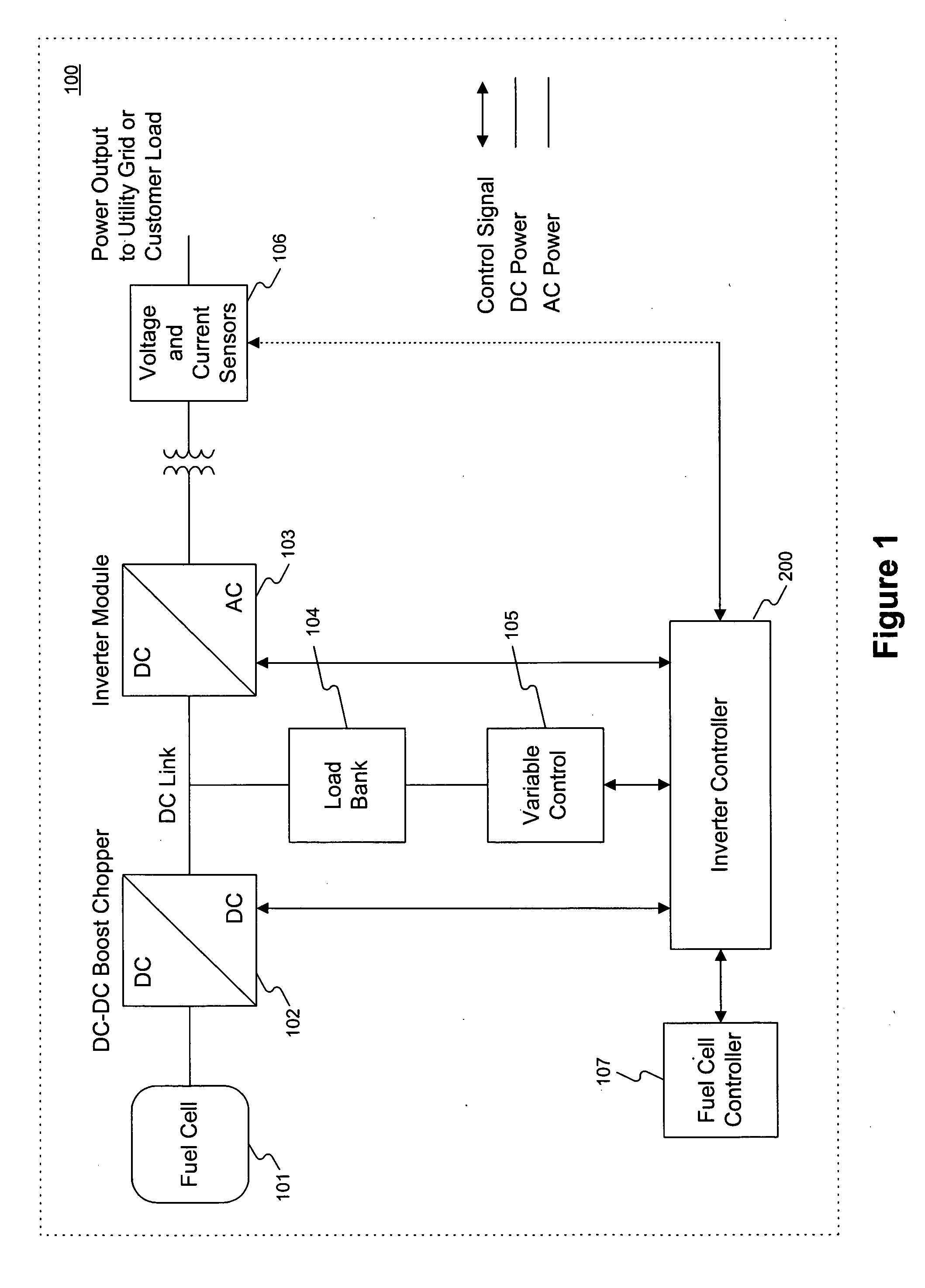
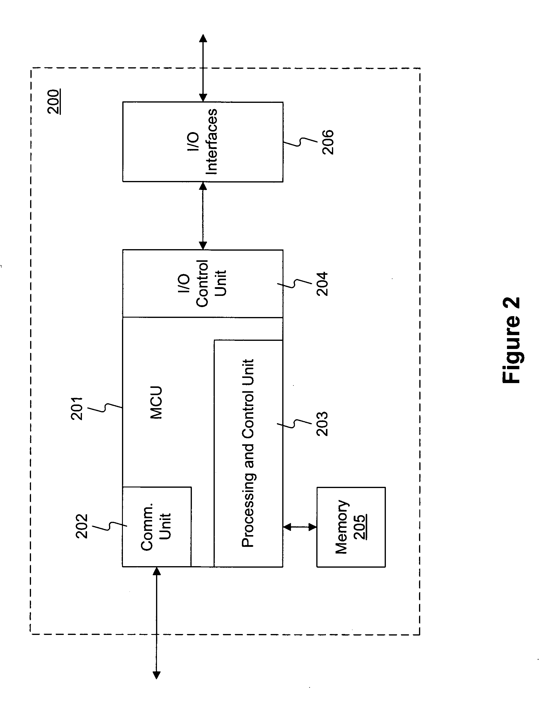
[0015]FIG. 1 illustrates an exemplary fuel cell power plant system 100 consistent with certain disclosed embodiments. As shown in FIG. 1, fuel cell power plant system 100 may include fuel cell 101, DC-DC boost chopper 102, inverter module 103, load bank 104, variable control unit 105, voltage and current sensors 106, fuel cell controller 107, and inverter controller module 200.

[0016] Fuel cell 101 generates DC electricity by using fuel cell technology. Fuel cell 101 may include a plurality of fuel cell stacks and associated fuel processing units. The fuel cell stacks in fuel cell 101 may use any type of fuel cell technologies, such as Proton Exchange Membrane Fuel Cell (PEMFC), Alkaline Fuel Cell (AFC), Phosphoric-Ac...


PUM

PropertyMeasurementUnit
chemical reaction rateaaaaaaaaaa
reaction rateaaaaaaaaaa

Abstract

Methods and systems are provided to control a fuel cell power plant system to provide load following capabilities and to improve power plant availability. In one embodiment, a method is performed for controlling a fuel cell power plant system. The process includes controlling a variable load bank capable of absorbing output power from the fuel cell power plant such that the total load on the fuel cell power plant is constant, wherein the total load is a combination of an external load connected to the power plant and a load on the variable load bank. Further, the process may include maintaining a constant chemical reaction rate of the fuel cell power plant while maintaining a desired total load.

Description

TECHNICAL FIELD [0001] This disclosure relates generally to power plant and load management systems, and particularly to methods and systems for providing load following capability and high availability for fuel cell power plants. BACKGROUND [0002] Fuel cell power plants have many advantages over conventional types of power plants. Particularly, most fuel cell power plants are more efficient and environment friendly than their conventional counterparts, since the fuel cell uses a catalyzed reaction between a fuel and an oxidizer to directly produce electricity. In order to continuously provide power to external consumers, fuels are continuously fed to fuel stacks of a fuel cell power generator based on a chemical reaction rate between the fuel and the oxidizer. When the electrical load on a fuel cell changes, chemical reactions must occur to maintain the output power level provided by the fuel cell. During operations of fuel cell power plants, such as those made of Molten Carbonate ...

Claims


Application Information

Patent Timeline
Patent Type & Authority Applications(United States)
IPC IPC(8): H01M8/04
CPCH01M8/04544H01M8/04574H01M8/04604H01M8/0494H01M8/04947Y02E60/50H02J1/14H02J3/387H02J2001/004H02M2001/007H01M2250/00H02J2300/30H02J3/381H02M1/007H02J3/46
Inventor LINDSEY, ROBERT WAYNE
Owner CATERPILLAR INC
Why Eureka
Try Eureka