
Structure for treating torch cable for arc welding robot

Inactive Publication Date: 2006-03-09
FANUC LTD
View PDF17 Cites 22 Cited by
  • Summary
  • Abstract
  • Description
  • Claims
  • Application Information

AI Technical Summary

Benefits of technology

[0017] Also, according to the second aspect, the torch cable is accommodated in a conduit to properly increase the rigidity of the torch cable itself. Thereby, it is possible to freely reciprocate the inserting guide in accordance with a force applied to the torch cable without adding a member for applying a drawing force. The torch cable is also guided by a sliding guide plate, whereby it is possible to maintain the stable behavior of the torch cable in the same manner as described above. By providing the inserting guide and the guiding plate, it is possible to always maintain the stable behavior of the torch cable along the front arm even if the robot wrist shaft operates.
[0023] According to the seventh aspect, the torch cable is accommodated in the conduit to properly increase the rigidity of the torch cable itself. Thereby, it is possible to freely reciprocate the inserting guide in accordance with a force applied to the torch cable without adding a member for applying a drawing force. The torch cable is also guided by a sliding guide plate, whereby it is possible to maintain the stable behavior of the torch cable in the same manner as described above. By providing the inserting guide and the guiding plate, it is possible to always maintain the stable behavior of the torch cable along the front arm even if the robot wrist shaft operates.
[0027] According to the present invention, in the arc welding robot of a ceiling-suspension type and a wall-hanging type, as the torch cable is not excessively drawn and thus not entangled with the front arm or the torch cable is not excessively loose or slackened and thus does not largely vary its curvature, it is possible to stabilize the delivery of the welding wire and the welding operation. Also, even if the ceiling-suspension type or the wall-hanging type is employed, a problem, in that it is difficult to dispose the welding torch at a position or posture suitable for the welding operation, is avoidable. Another advantage is that almost all elements used in the inventive structure for treating or handling the torch cable are common to those used in the system disclosed in Japanese Patent Application No. 2004-194593. Thus, it is possible to provide the most suitable structure for treating or handling the torch cable in accordance with various conditions for installing the robot by only adding and / or exchanging a minimum number of members, so that it is economical to use the structure of the present invention.

Problems solved by technology

On the contrary, the torch cable is liable to interfere with the periphery of the arm or the welding torch.
This is because the torch cable is in a loose state or a slackened state to deliver the welding torch in a stable state, which, however, widens the area to interfere with the periphery.
If the robot base 15 is fixed to the ceiling in the above structure so that the robot is inverted as a whole, there is a difficulty due to the limitation of the operative range of the wrist axis.
That is, the operative range of the first and second wrist elements is limited to be narrower than ±180 degrees due to the restriction of flexibility of the torch cable, and when the robot is suspended from the ceiling, there has been a problem to be solved in that the operation becomes difficult in a state wherein a tip end of the torch is directed upward or downward.

Method used


Image

  • Structure for treating torch cable for arc welding robot
  • Structure for treating torch cable for arc welding robot
  • Structure for treating torch cable for arc welding robot

Examples


first embodiment

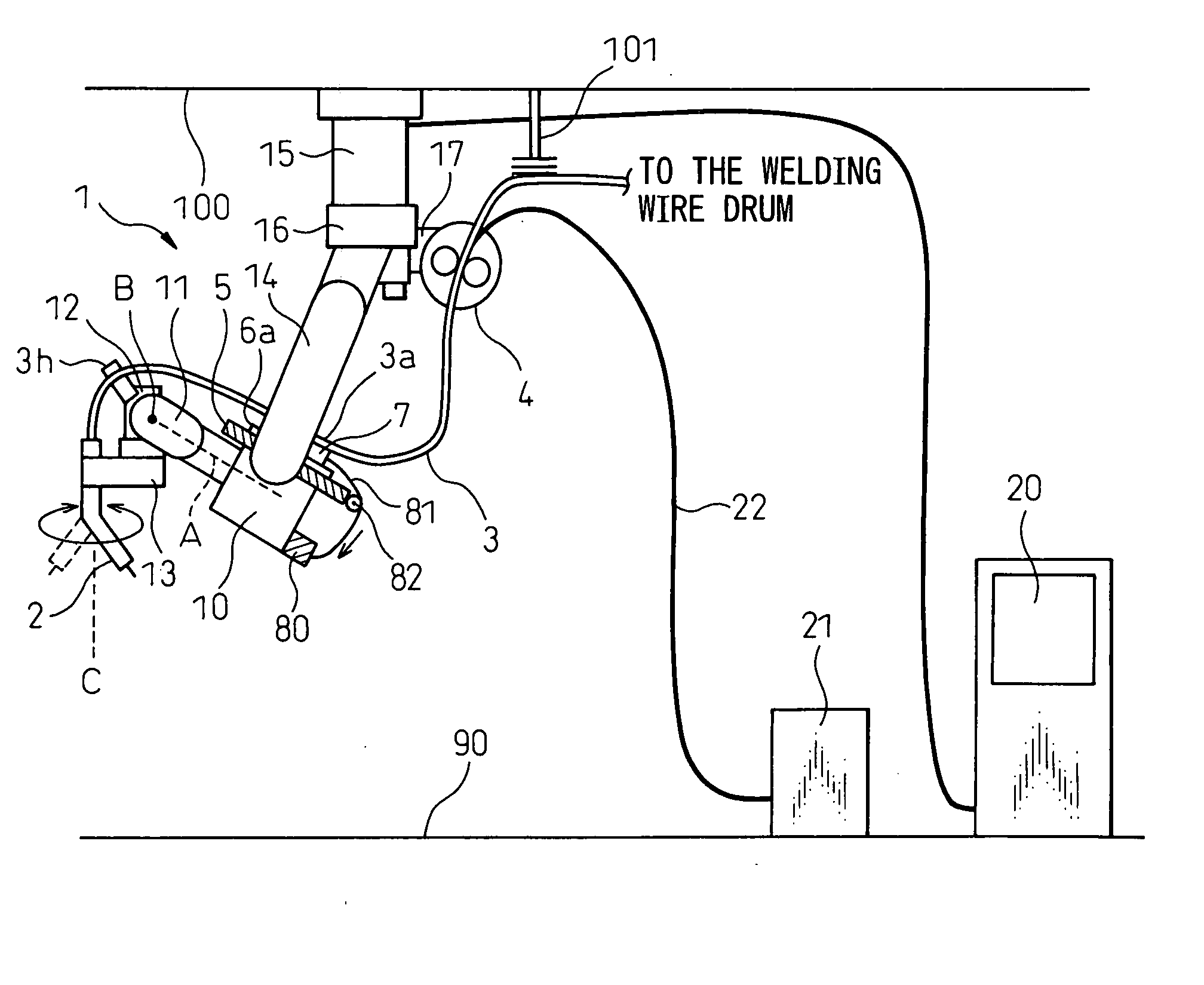
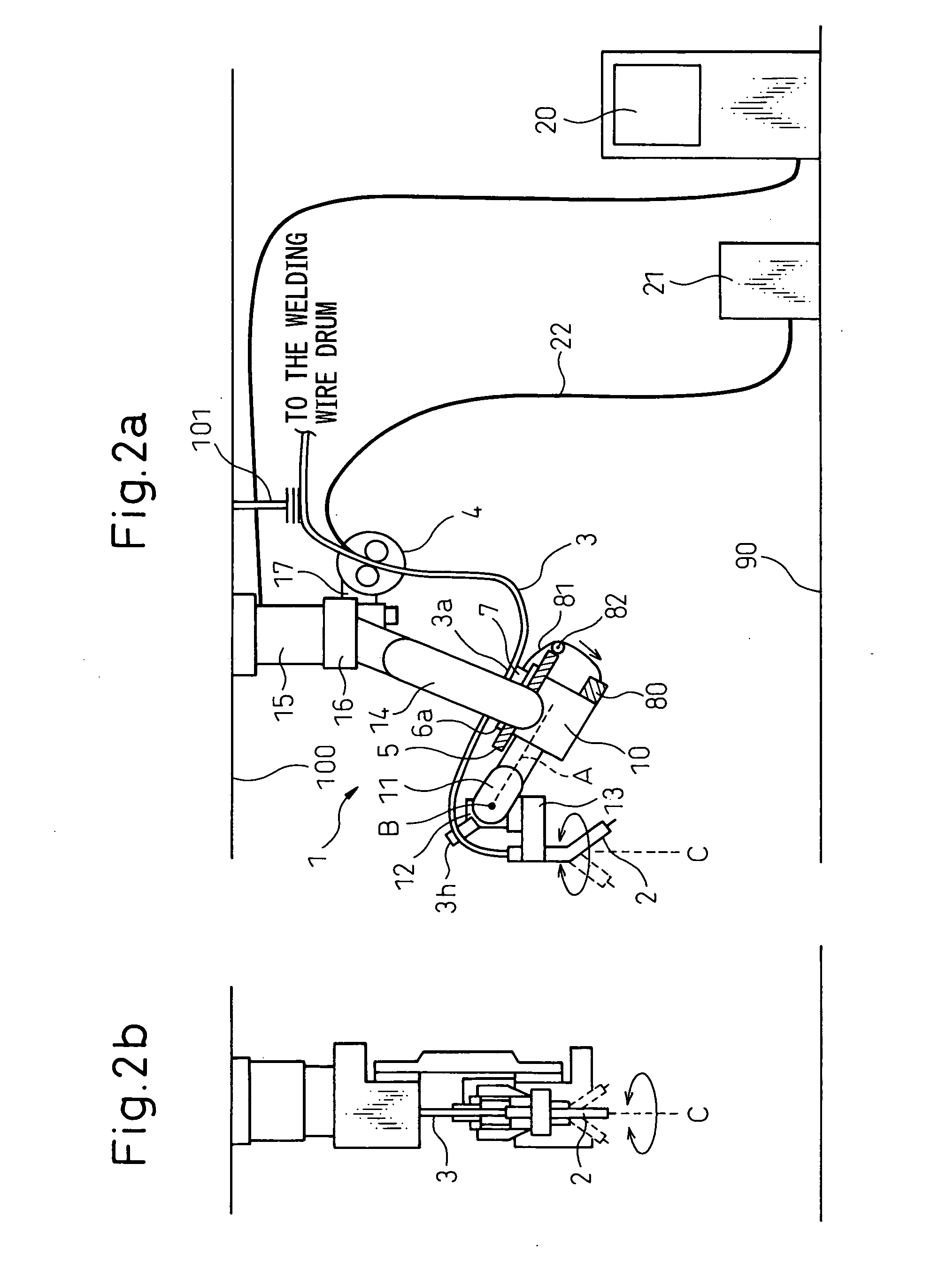
[0044] Embodiments of the present invention will be described below with reference to the drawings. FIGS. 2a and 2b illustrate a front view and a right side view, respectively, of an overall structure of an arc welding robot according to the present invention. Reference 1 denotes an arc welding robot of a six-axes type, a robot base 15 of which is installed not on a floor surface 90 but on a ceiling 100 whereby an upper arm 14 extends downward from the robot base 15. At a tip end of a front arm base 10, a first wrist element 11 is provided to be rotatable about a first axis A, and a second wrist element 12 is provided on the first wrist element 11 to be rotatable about a second axis B.

[0045] A welding torch 2 is supported on the second wrist element 12 via a transmission mechanism 13 to be rotatable about a third axis C disposed at a predetermined distance from the first axis A while remaining generally vertical to the second axis B, whereby the welding torch 2 is rotatable about th...

fourth embodiment

[0062]FIGS. 4a and 4b illustrate a front view and a top view, respectively, of an overall structure of an arc welding robot according to the present invention. In this embodiment, a robot base 15 of an arc welding robot 1 is provided in a wall extending upward from a floor surface 90 toward a ceiling 100, and an upper arm 14 extends from the robot base 15 in the lateral direction. At a tip end of a front arm base 10 attached to the vicinity of a tip end of the upper arm 14, a first wrist element 11 is provided to be rotatable about a first axis A, and a second wrist element 12 is provided on the first wrist element 11 to be rotatable about a second axis B.

[0063] A welding torch 2 is supported by the second wrist element 12 via a transmission mechanism 13 (a concrete example thereof will be described later) to be rotatable about a third axis C extending generally vertical to the second axis B and away from the first axis A at a predetermined distance. The welding torch 2 is rotatable...

fifth embodiment

[0073]FIG. 5b illustrates one modification of the In the embodiment shown in FIG. 5b, the slide mechanism is eliminated and, instead, a structure in which an inserting guide 3h is directly provided on a front base 10 is employed. The inserting guide 3h is designed to have a guide hole larger than an outer diameter of the torch cable 3, so that the torch cable 3 freely reciprocates generally parallel to the longitudinal direction of the front arm. Also, as illustrated, a inserting guide 3h′ is also provided on the first wrist element 11 to hold the torch cable 3. Even if the robot wrist shaft operates, the torch cable is maintained in a stable state by these inserting guides 3h and 3h′ while being always along the front arm. As illustrated, the inserting guide 3h is rotatable about a rotary axis on a bearing.

[0074] In the arc welding robot of a wall-hanging type according to this embodiment in which the torch cable is clamped on the slide mechanism, even if the posture of the weldin...


PUM

PropertyMeasurementUnit
Forceaaaaaaaaaa

Abstract

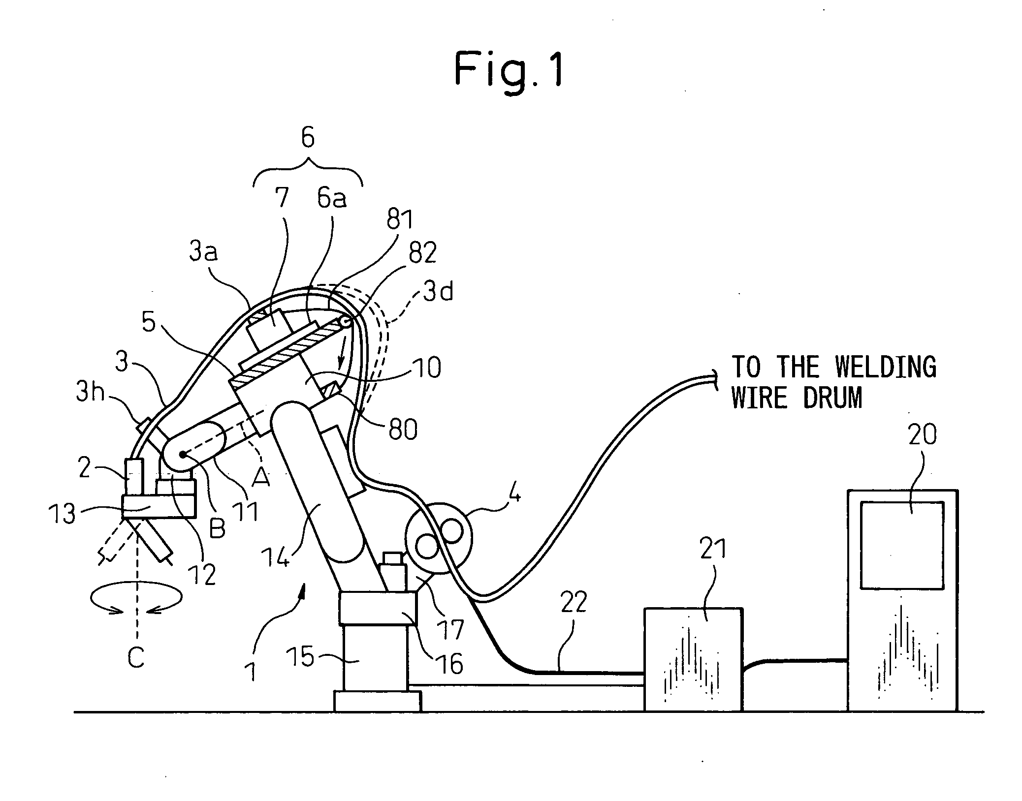
A robot base 15 is installed on a ceiling 100, and a first wrist element 11 is attached to a front arm base 10 to be rotatable about a first axis A. A second wrist element 12 is attached to the first wrist element 11 to be rotatable about a second axis B, and a welding torch 2 is supported via a transmission mechanism 13 to be rotatable about an offset axis C. The welding torch 2 is attached so that a tip end thereof is directed downward in the illustrated posture of the robot. A linear guide 6a and a slider 7 are provided via a support base 5, and an intermediate portion of a torch cable 3 (or a welding wire delivery device 4) is fixed thereto to draw a tensioning device 80. Such a structure is applicable to a wall-hanging type robot. Thereby, a structure for treating a torch cable is realized in an arc welding robot of a ceiling-suspension type / a wall-hanging type, capable of maintaining the behavior of the torch cable in a stable state as well as minimizing the interference of the torch cable with other objects.

Description

BACKGROUND OF THE INVENTION [0001] 1. Field of the Invention [0002] The present invention relates to a structure for treating or handling a torch cable for an industrial robot carrying out arc welding (hereinafter referred to an arc welding robot or merely to a robot) and, particularly, to a structure for treating or handling a torch cable for an arc welding robot of a ceiling-suspension type or a wall-hanging type. [0003] 2. Description of the Related Art [0004] An arc welding robot often carries out a welding operation while inserting an arm or a welding torch provided at a distal end of the robot into a narrow gap between the work, a jig and peripheral equipment. In such a case, there is no problem about the arm or the welding torch provided at a distal end of the robot since an area in which the arm or the welding torch may interfere with the periphery is narrow. On the contrary, the torch cable is liable to interfere with the periphery of the arm or the welding torch. This is b...

Claims


Application Information

Patent Timeline
IPC IPC(8): B23K9/32
CPCB23K9/1336B23K9/28B23K9/287B23K37/02B25J9/0018
Inventor NIHEI, RYOINOUE, TOSHIHIKONAKAYAMA, KAZUTAKAIWAYAMA, TAKATOSHI
Owner FANUC LTD
Learn More