Controller of glow plug and glow plug

a control device and glow plug technology, applied in the direction of electric control, lighting and heating apparatus, machines/engines, etc., can solve the problems of unlikely defective conditions such as temperature changes in the heater according to the speed of combustion gas colliding with the heater surface, and achieve the effect of preventing mechanical switch adhesion or breakage, stably maintaining the heater amount, and resisting the heating element. varies rapidly and greatly

Inactive Publication Date: 2006-03-09
NGK SPARK PLUG CO LTD
View PDF19 Cites 15 Cited by
  • Summary
  • Abstract
  • Description
  • Claims
  • Application Information

AI Technical Summary

Benefits of technology

[0038] The resistive heating element is directly and promptly influenced by the cooling of the heater due to fuel injection and combustion gas, when the resistive heating element of the glow plug has a ratio R1000 / R20 of 6 or larger and at least partly protrudes in the engine combustion chamber. The resistance of the resistive heating element varies quickly and greatly in response to heater cooling. It is thus possible to adjust the electrical power supplied to the heater to its target value promptly and properly and thereby possible to stably maintain the amount of heater generated by the heater.
[0039] As the resistive heating element is installed in the sheath tube in connection with the front end of the sheath tube, it is possible to arrange the resistive heating element easily so as to protrude in the combustion chamber at the occasion of mounting the glow plug on the engine block with the resistance heater being protrudingly located in the combustion chamber.
[0040] When the inrush current limiting resistor is connected in series with the rear end of the resistive heating element, the composite resistance of the resistive heating element and the inrush current limiting resistor becomes increased to limit the passage of a large current through the resistive heating element at the initial stage of energization. This makes it possible to prevent adhesion of the mechanical switch or breakage of the semiconductor switch. In view of the resistance characteristic of the resistive heating element, the resistance of the inrush current limiting resistor can be selected appropriately so as to prevent the adhesion of the mechanical switch or the breakage of the semiconductor switch. It is however desirable to select the resistance of the inrush current limiting resistor in such a manner that the composite resistance R20 of the resistive heating element and the inrush current limiting resistor at 20° C. becomes 100 mΩ or higher, for the reason that the power supply voltage is normally 12 V.
[0041] Preferably, the inrush current limiting resistor has a smaller ratio R1000 / R20 of electrical resistance R1000 at 1000° C. to electrical resistance R20 at 20° C. than that of the resistive heating element. This makes it possible to increase the amount of heat generated by the resistive heating element on the front end side of the resistance heater and thereby possible to preheat the inside of the engine combustion chamber effectively.

Problems solved by technology

In addition, defective conditions such as temperature changes in the heater according to the speed of combustion gas colliding with the heater surface become unlikely to occur.

Method used


Image

  • Controller of glow plug and glow plug
  • Controller of glow plug and glow plug
  • Controller of glow plug and glow plug

Examples


first embodiment

[0064] the present invention will be explained.

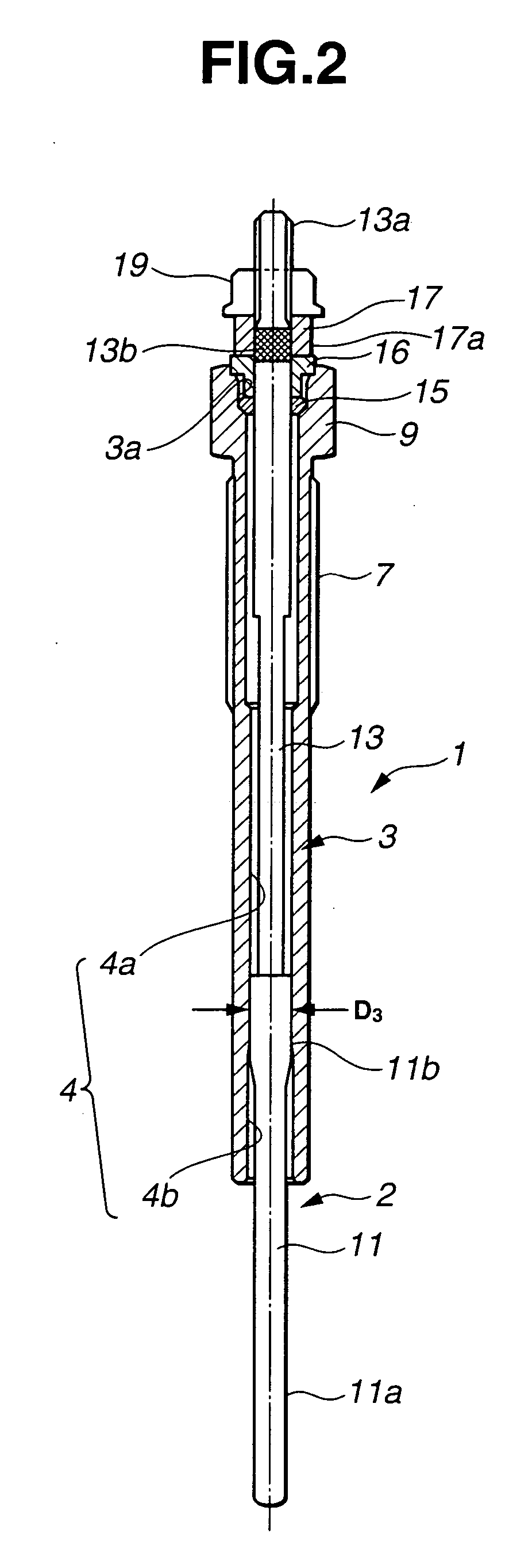
[0065]FIG. 2 is a schematic view of a glow plug according to the first embodiment of the present invention. FIG. 3A is a section view of a sheath heater of the glow plug of FIG. 2, and FIG. 3B is a partial enlarged view of an inner structure of the sheath heater of FIG. 3A. A glow plug 1 includes a sheath heater 2 as a resistance heater and a metallic shell 3 disposed around the sheath heater 2. The sheath heater 2 has a sheath tube 11 with a closed front end, a plurality of resistive wire coils, e.g., two resistive wire coils in the first embodiment including a heating coil 21 (as a first resistive heating element: heating element) located on the front end side and a control coil 23 (as a second resistive heating element: resistive heating element) located on the rear end side in series connection with the heating coil 21, and an electrically insulating material of magnesia powder 27 with which these coils 21 and 23 are sealed in the s...

second embodiment

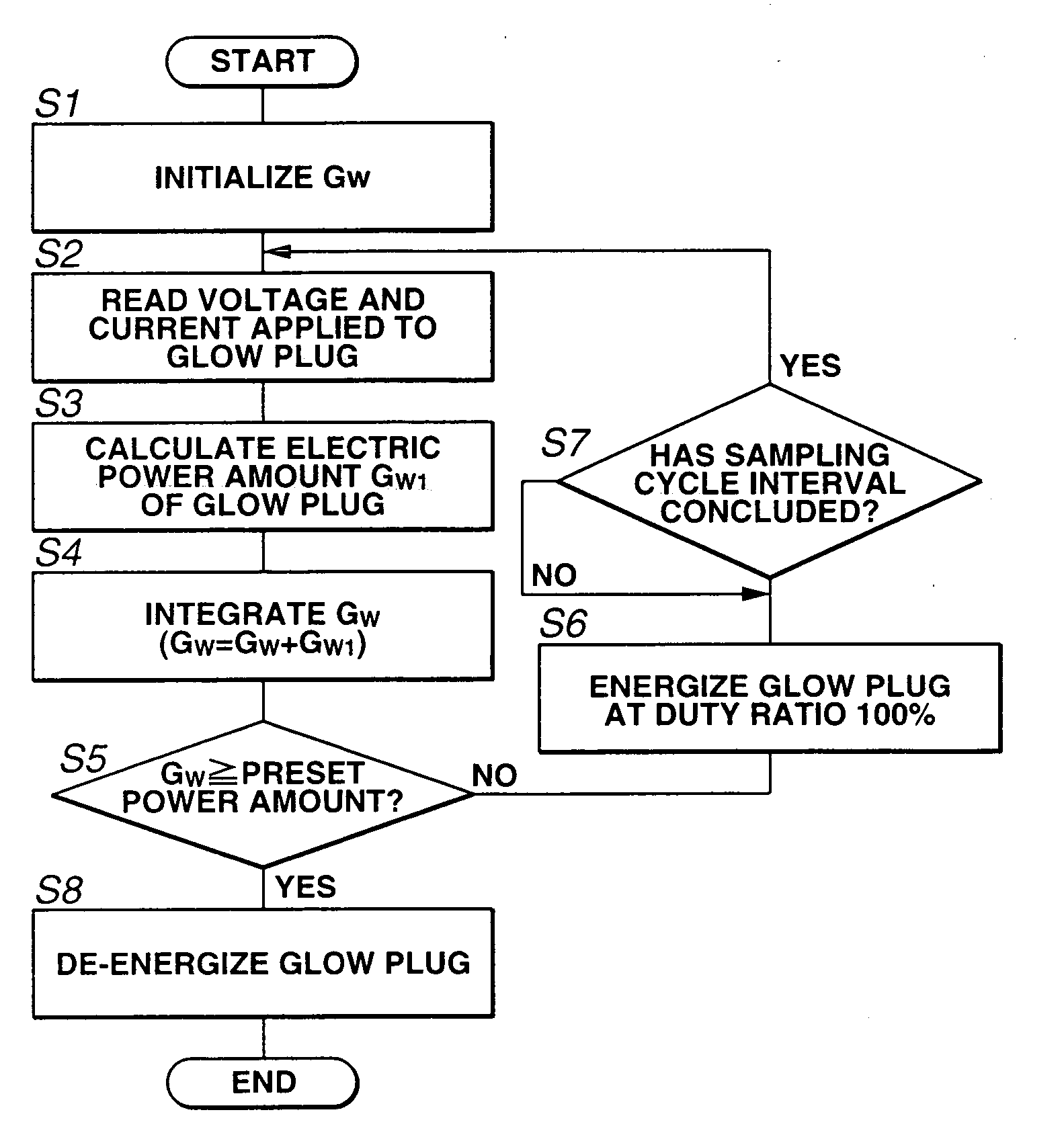
[0124]FIG. 7 shows a processing example of the management of the duration of the transient control mode in the This management processing is aimed to determine the timing of finishing the transient control mode depending on whether the heater resistance Ri has reached a saturation value without setting the duration of the transient control mode fixedly. A maximum limit is set on the duration of the transient control mode. In step S121, an elapsed-time counter TS2 first is initialized. In step S122, the plug applied voltage Vx is retrieved. In step S123, the reference duty ratio η0 for the transient control mode is determined according to the plug applied voltage Vx. The plug applied current Ix is also retrieved in step S122. In step S124, the elapsed-time counter TS2 is incremented by a Vx sampling cycle time. In step S125, the heater resistance Ri is calculated from the retrieved voltage Vx and current Ix. In step S126, it is checked whether i=1 or not (i.e. whether the calculated...


PUM


Abstract

There is provided a control device for a glow plug, capable of controlling the energization of a resistance heater of the glow plug by a resistance control process while attaining good resistance control response under cooling of the heater by fuel injection and combustion gas and thereby stably controlling the amount of heat generated by the heater. The resistance heater includes a resistive heating element having a ratio of electrical resistance R1000 at 1000° C. to electrical resistance R20 at 20° C. of 6 or larger, and the glow plug is mounted with at least part of the resistive heating element being protrudingly located in an engine combustion chamber. Under such a condition, the control device controls energization of the resistance heater in a steady control mode to adjust electrical power supplied to the resistance heater in such a manner as to keep a resistance of the heater within a predetermined range.

Description

TECHNICAL FIELD [0001] The present invention relates to a glow plug control device and a glow plug used for the preheating of a diesel engine and the like. BACKGROUND ART [0002] A glow plug for the preheating of a diesel engine and the like is generally equipped with a resistance heater (hereinafter occasionally just referred to as a “heater”). This glow plug is assembled by fixing the resistance heater in a metallic shell, and mounted onto the engine block of a diesel engine by means of a thread cut in an outer cylindrical surface of the metallic shell in such a manner that a front heating end portion of the resistance heater is located within an engine combustion chamber. [0003] The resistance heater includes a resistive heating element (made of a resistive heating wire or an electrically conductive ceramic material) with a positive temperature coefficient of resistance, so that the electrical resistance of the heating element increases with temperature upon energization of the he...

Claims


Application Information

Patent Timeline
Patent Type & Authority Applications(United States)
IPC IPC(8): F23Q7/22F02P19/02F23Q7/00
CPCF02D41/22F02D2041/2027F23Q7/001F02P19/022F02P19/025F02D2041/2031
Inventor GOTOH, SHUNSUKEKUMADA, CHIAKIKIMATA, HIROYUKIMURAMATSU, SEIGOSAKURAI, TAKAYUKI
Owner NGK SPARK PLUG CO LTD
Why Eureka
Try Eureka