Liquid crystal device and projection display device

a technology of liquid crystal and projection display, which is applied in the direction of instruments, non-linear optics, optics, etc., can solve the problems of reducing the contrast ratio of the projected image, not as good as the projector, etc., and achieves negative refractive index anisotropy, excellent optical compensation, and high contrast

Inactive Publication Date: 2006-03-09
SEIKO EPSON CORP
View PDF4 Cites 15 Cited by
  • Summary
  • Abstract
  • Description
  • Claims
  • Application Information

AI Technical Summary

Benefits of technology

[0006] An advantage of the invention is that it provides a projection display device which is capable of performing excellent optical compensation even when the liquid crystal is pretilted, and of performing image display having a high contrast by including a liquid crystal device of the invention.
[0007] According to an aspect of the invention, a liquid crystal device includes a pair of substrates; a liquid crystal layer interposed between the pair of substrates, the liquid crystal layer being composed of liquid crystal having negative dielectric anisotropy representing that an initial alignment state thereof is vertical; and an optical compensating plate which is provided outside at least one substrate of the pair of substrates and has negative refractive index anisotropy. The liquid crystal is pretilted in a predetermined direction, and an optical axis direction of the optical compensating plate is substantially parallel to the pretilt direction of the liquid crystal. In the above-mentioned liquid crystal device, it is preferable that the optical compensating plate be disposed parallel to one substrate, and the optical axis direction of the optical compensating plate be substantially parallel to the pretilt direction of the liquid crystal, at an angle deviating from the normal line of the optical compensating plate. Further, preferably, the optical axis direction of the optical compensating plate is substantially parallel to the normal line direction of the optical compensating plate, and the optical compensating plate be disposed to be inclined from a location parallel to one of the pair of substrates such that the optical axis direction of the optical compensating plate is substantially parallel to the pretilt direction of the liquid crystal.
[0008] In this case, the optical axis direction of the optical compensating plate is inclined according to the pretilt of the liquid crystal, so that it is possible to entirely compensate for a phase difference due to the pretilt of the liquid crystal and a phase difference due to the light in a inclined direction.
[0009] According to another aspect of the invention, there is provided a projection display device including the above-mentioned liquid crystal device as an optical modulating unit.
[0010] In this case, light leakage in black display can be prevented, and a high contrast ratio in a projected image can be obtained.
[0011] Further, preferably, the projection display device further includes an adjuster that adjusts an arrangement angle of the optical compensating plate such that the optical axis direction of the optical compensating plate aligns with the pretilt direction of the liquid crystal. Furthermore, it is preferable that the adjuster be composed of a rotation mechanism for rotating the optical compensating plate on two axes.

Problems solved by technology

However, since most liquid crystal projectors in the related art have a contrast ratio of substantially 1:500 in a projected image, they are not as good as projectors, such as DMDs (registered trademark) using mechanical shutters, which have a contrast ratio of 1:3000.
However, since the liquid crystal device has incident angle dependence, it causes the contrast ratio of the projected image to decrease.

Method used


Image

  • Liquid crystal device and projection display device
  • Liquid crystal device and projection display device
  • Liquid crystal device and projection display device

Examples


first embodiment

[0028] First, a liquid crystal device according to a first embodiment of the invention will be described with reference to FIGS. 1 to 6. The liquid crystal device according to the first embodiment includes a liquid crystal panel with a liquid crystal layer interposed between a pair of substrates, an optical compensating plate disposed outside one substrate of the liquid crystal panel, and polarizers disposed outside the optical compensating plate and the other substrate of the liquid crystal panel, respectively. In the present embodiment, an active-matrix-type transmissive liquid crystal panel, which uses a thin film transistor (hereinafter, referred to as a TFT) element serving as a switching element, will be described by way of an example.

Equivalent Circuit

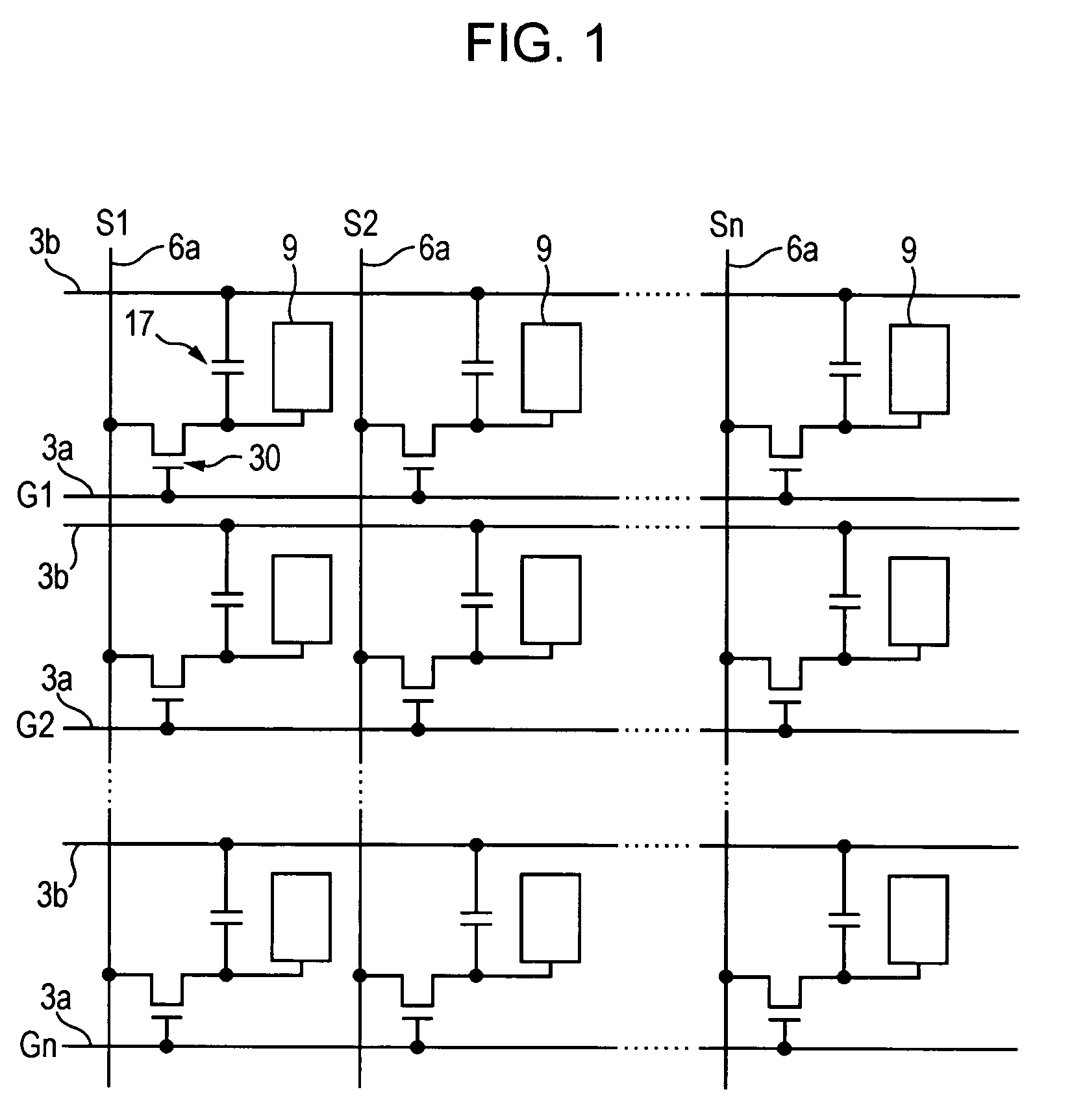
[0029]FIG. 1 is an equivalent circuit diagram of the liquid crystal panel. A plurality of dots arranged in a matrix which constitute an image display region of the transmissive liquid crystal panel are provided with pixel ele...

second embodiment

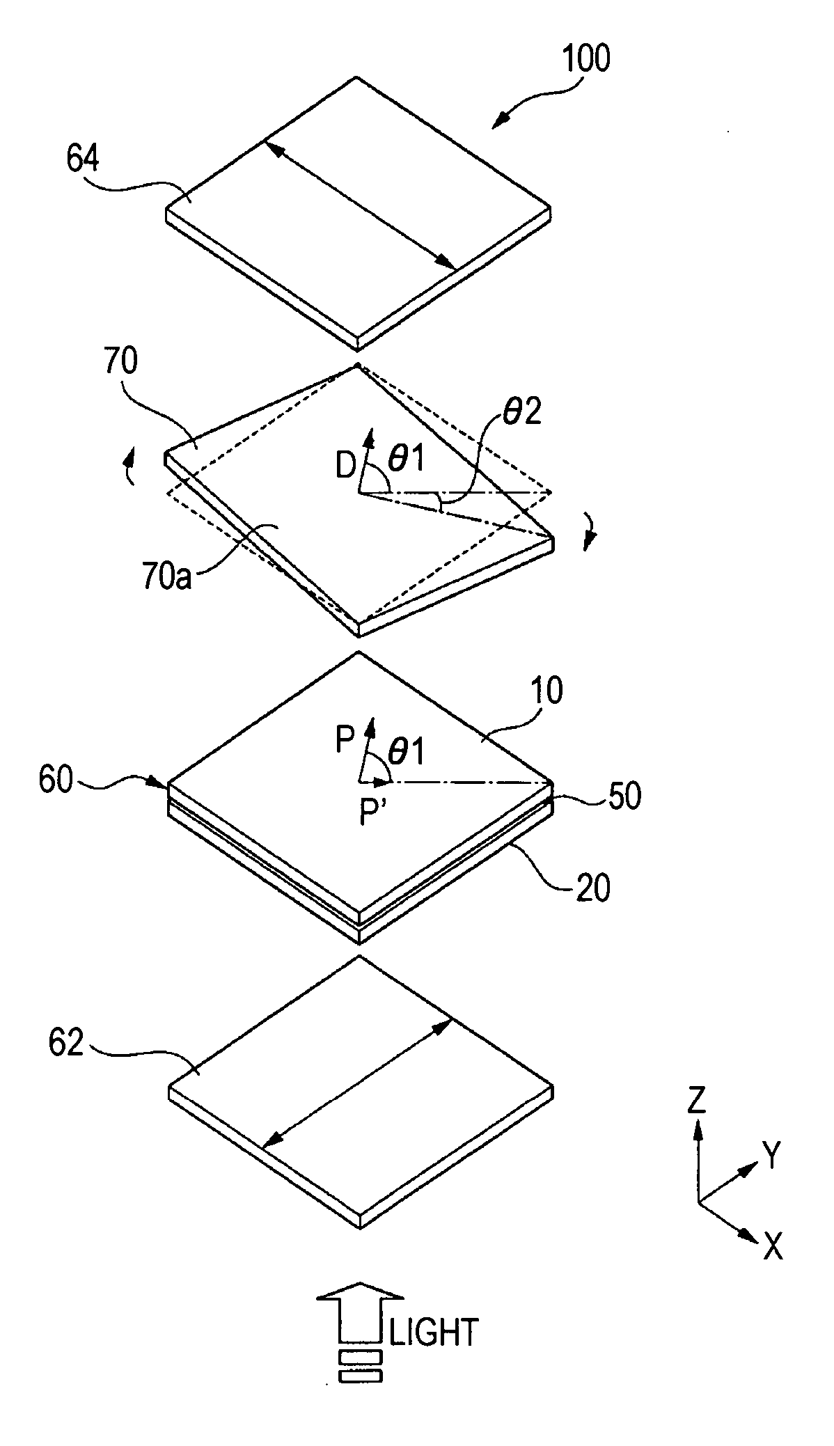
[0051] Next, a liquid crystal device according to a second embodiment of the invention will be described with reference to FIGS. 7 to 9. The liquid crystal device according to the present embodiment has the same basic configuration as that of the first embodiment, except that an optical compensating plate is disposed parallel to a liquid crystal panel and only its optical axis is inclined from a horizontal plane. Therefore, in FIGS. 7 to 9, constituent elements common to FIGS. 1 to 6 are denoted by the same reference numerals, and the description thereof will be omitted.

[0052]FIG. 7 is an exploded perspective view of the liquid crystal device according to the second embodiment of the invention.

[0053] A liquid crystal device 200 according to the present embodiment includes a liquid crystal panel 60, an optical compensating plate 80 disposed outside a TFT array substrate 10 of the liquid crystal panel 60, and polarizers 62 and 64 disposed outside the optical compensating plate 80 an...


PUM

PropertyMeasurementUnit
pretilt angleaaaaaaaaaa
thicknessesaaaaaaaaaa
angleaaaaaaaaaa

Abstract

A liquid crystal device includes a pair of substrates; a liquid crystal layer interposed between the pair of substrates, the liquid crystal layer being composed of liquid crystal having negative dielectric anisotropy in which an initial alignment state thereof is vertical; and an optical compensating plate which is provided outside at least one substrate of the pair of substrates and has negative refractive index anisotropy. The liquid crystal is pretilted in a predetermined direction, and an optical axis direction of the optical compensating plate is substantially parallel to the pretilt direction of the liquid crystal.

Description

BACKGROUND OF THE INVENTION [0001] 1. Technical Field [0002] The present invention relates to a liquid crystal device and to a projection display device. [0003] 2. Related Art [0004] In recent years, liquid crystal projectors (projection display devices) have been used as display devices in which large-screen display can be performed. In such a projector, a structure has been suggested in which a liquid crystal device, which is driven in a ‘VA (Vertical Alignment) mode’ where liquid crystal having negative dielectric anisotropy is vertically aligned on a substrate and liquid crystal molecules are tilted by applying a voltage, is included as a light valve. However, since most liquid crystal projectors in the related art have a contrast ratio of substantially 1:500 in a projected image, they are not as good as projectors, such as DMDs (registered trademark) using mechanical shutters, which have a contrast ratio of 1:3000. That is because of the viewing angle characteristics of the liq...

Claims


Application Information

Patent Timeline
Patent Type & Authority Applications(United States)
IPC IPC(8): G02F1/1335
CPCG02F1/13363G02F2413/11G02F2413/10G02F2413/01G02F1/133634G02F1/1335
Inventor HARUYAMA, AKIHIDE
Owner SEIKO EPSON CORP
Why Eureka
Try Eureka