Acoustic actuators

a technology of actuators and actuators, applied in the direction of transducer types, frequency/directions obtaining arrangements, electrical apparatus, etc., can solve the problems of high voltage, low piezo actuators, and unsuitable physical profiles for some applications, and achieve the effect of improving the bass response of panel loudspeakers

Inactive Publication Date: 2006-03-09
FEONIC
View PDF5 Cites 10 Cited by
  • Summary
  • Abstract
  • Description
  • Claims
  • Application Information

AI Technical Summary

Benefits of technology

[0021] It has surprisingly been found that the provision of an open hole or passageway between the interior of the recess and the outer surface of the reaction mass significantly enhances the bass response of the panel loudspeaker of which the device forms a part. A circular passageway having a diameter of around 4 mm has been found to be effective, although other configurations may also be beneficial.

Problems solved by technology

The method of construction of these actuators means that although they deliver high force they have a physical profile that is unsuitable for some applications.
However piezo actuators deliver comparatively low forces, require high voltages, about 100 v, and are unsuitable for acoustic applications at frequencies below about 1 KHz.
Higher force stacked piezo actuators are available but these are expensive, difficult to manufacture and tend to be unreliable.
The height of the stack may also create an unacceptable profile.
One potential solution to providing a high force, low profile actuator has been to use a flex-tensional envelope around an active element, as disclosed in USA4845688, that may be a magnetostrictive or piezo engine, but this is still too bulky for many applications.
It has been found through experimentation and trial that distortion of the output acoustic signal generated by such a device, particularly when miniaturised, can arise through the annular spring allowing a non-predictable extension to the driven face, resulting in an off-square output force which compromises the audio output.

Method used


Image

  • Acoustic actuators
  • Acoustic actuators
  • Acoustic actuators

Examples


Embodiment Construction

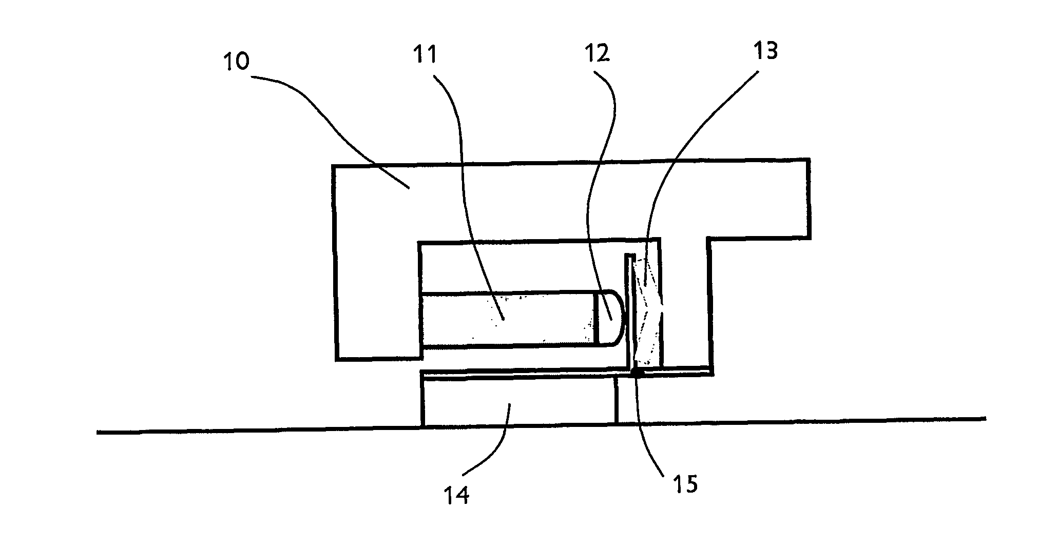
[0032] Referring first to FIG. 1, an active element 11 is mounted generally horizontally on an inertial or back mass 10 which is attached to a foot 14 through a resiliently flexible plate 15 acting as a solid-state hinge. A bearing plate 16 extends normally to the hinge and is engaged by a curved bearing surface 12 mounted on the end of the active element 11. A leaf spring 13 is mounted between the bearing plate 16 and the back mass 10 so as to apply controlled pre-tension to the active element. The active element thus drives horizontally, and the construction of the actuator converts this motion into a vertically acting force using the hinge, which is preferably a solid-state hinge to reduce energy losses. A hinge with a pin and / or bearing surface would generate unacceptable losses because of the small amplitude of the movements involved. The curved bearing surface 12 may be part of the element or is more conveniently a separate piece of material of low compliance.

[0033] In the ca...


PUM


Abstract

An acoustic transducer comprises an active element (21) which changes in length along a first axis in response to an audiofrequency input signal, the element being mounted between an inertial mass (20) and a foot (24) which in use engages a surface whereby audiofrequency vibrations produced by the active element are transmitted to the surface, characterised in that the foot is hingedly (25) connected to the inertial mass and the active element is located between the foot and the mass such that the angle between the first axis and the surface is less than 90°, in use.

Description

FIELD OF THE INVENTION [0001] This invention relates to acoustic actuators, for example of the type used to drive panel-type acoustic radiators. BACKGROUND TO THE INVENTION [0002] Direct drive actuators employing active elements which are rods of magnetostrictive material are well-known. Examples of such actuators are disclosed and claimed in our published International Application WO 02 / 076141. The method of construction of these actuators means that although they deliver high force they have a physical profile that is unsuitable for some applications. Other active elements such as piezo can be incorporated into actuators that have a flat or narrow profile and may be suitable for many of the applications where a magnetostrictive actuator is unsuitable. However piezo actuators deliver comparatively low forces, require high voltages, about 100 v, and are unsuitable for acoustic applications at frequencies below about 1 KHz. For these reasons piezo actuators may not be used. Higher fo...

Claims


Application Information

Patent Timeline
Patent Type & Authority Applications(United States)
IPC IPC(8): H04R25/00H04R7/04H04R15/00H04R17/00
CPCH04R1/24H04R1/26H04R2440/05H04R15/00H04R17/00H04R7/045
Inventor METHERINGHAM, WILLIAM JOHNJOHNSON, DAVID ANTHONYSMITH, BRIAN DOUGLASMUNNS, NEILASTON, MARTIN GEOFFREY
Owner FEONIC
Why Eureka
Try Eureka