Method and apparatus for generating drive signals for loudspeakers

a technology of drive signal and loudspeaker, applied in the direction of electrical apparatus, stereophonic systems, etc., can solve the problems of unbalanced bass response, increased complexity, flexibility and capability of offered solutions, unpleasant perception of so-called “boomy bass”, etc., to improve bass response, improve audio reproduction, and reduce sensitivity to specific loudspeaker positions

Inactive Publication Date: 2016-08-18
KONINKLJIJKE PHILIPS NV
View PDF4 Cites 2 Cited by
  • Summary
  • Abstract
  • Description
  • Claims
  • Application Information

AI Technical Summary

Benefits of technology

[0014]The invention may allow improved audio reproduction in many scenarios and embodiments. In particular, it may allow an improved bass response in many embodiments and may achieve a reduced sensitivity to specific loudspeaker positions and / or characteristics of the acoustic environment. Specifically, a reduced acoustic sensitivity to and impact of room resonances in the room may be achieved.
[0015]The approach may specifically reduce the impact and sensitivity to room resonances without resulting in the introduction of notches in the spectrum of the rendered or perceived audio. Specifically, the approach may allow the rendered sound to not be attenuated at frequencies corresponding to strong room resonances. In many scenarios, the excitation of room resonances may be reduced or prevented while still allowing audio to be rendered at the corresponding frequencies.

Problems solved by technology

This has resulted in an increasing complexity, flexibility and capability of the offered solutions.
However, a common problem with sound reproduction, particularly in small- to mid-sized spaces such as rooms in a private home, conference rooms, studios, etc., is unbalanced bass response caused by standing waves that are related to so-called room modes.
As a consequence, such narrow bands may appear to be amplified significantly (by the acoustic response of the room) leading to an unpleasant perception of so-called “boomy” bass.
Indeed, the attenuation may be to such an extent that the frequencies are essentially absent in the perceived sound, leading to a perception of overall lack of power and a lack of spectral balance.
Moreover, these described problems are typically very position-dependent, and accordingly a frequency band that may be overly prominent (“boomy”) at one listening position, may be almost absent in another listening position.
This problem is in particular difficult to solve satisfactorily by means of signal processing since it is inherently caused by the physical and geometrical properties of the room.
Furthermore, it is an issue which has significant practical implications as it can potentially occur with any sound reproduction system, and in particular sound reproduction systems that are capable of reproducing frequencies below, say, 150-200 Hz.
However, typically this does not remove the effect unless the problematic frequency bands are almost completely removed in the source signal.
This is because the problem is caused by a strong resonance of the room, which needs only very little energy to be excited.
However, a substantially complete removal of frequency bands is not a desirable solution as it distorts the sound.
In particular, it tends to result in perceptible “drop-outs” in the bass portion of the rendered audio and an overall perception of a lack of power or impact of the rendered audio.
However, a fundamental short-coming of these prior art approaches is that they tend to distort the overall frequency response of the rendered audio, and / or to improve the response only at a single or a few reference positions (where the measurement was performed) while distorting the sound reproduction at other positions.
Indeed, the main problem of addressing the spatial variations and spectral balance of, in particular, the bass level throughout the room is not solved by such approaches.
While this concept is reported in the literature to be effective, it is not an attractive solution for many implementations and in particular not for consumer applications.
Firstly, such systems require the loudspeakers to be carefully placed in very specific locations, which is contrary to the trend in the consumer market towards freedom of placement.
Secondly, it is an inefficient solution, since the generated cancellation sound waves produced by the additional speakers have the same power as the original sound waves, and thus the required power is doubled.
Furthermore, in many practical implementations the requirement of having additional speakers merely to perform such compensation purposes is unacceptable.

Method used


Image

  • Method and apparatus for generating drive signals for loudspeakers
  • Method and apparatus for generating drive signals for loudspeakers
  • Method and apparatus for generating drive signals for loudspeakers

Examples


Embodiment Construction

[0063]The following description focuses on embodiments of the invention applicable to a system for rendering an audio signal using e.g. a surround sound loudspeaker setup with a plurality of speakers.

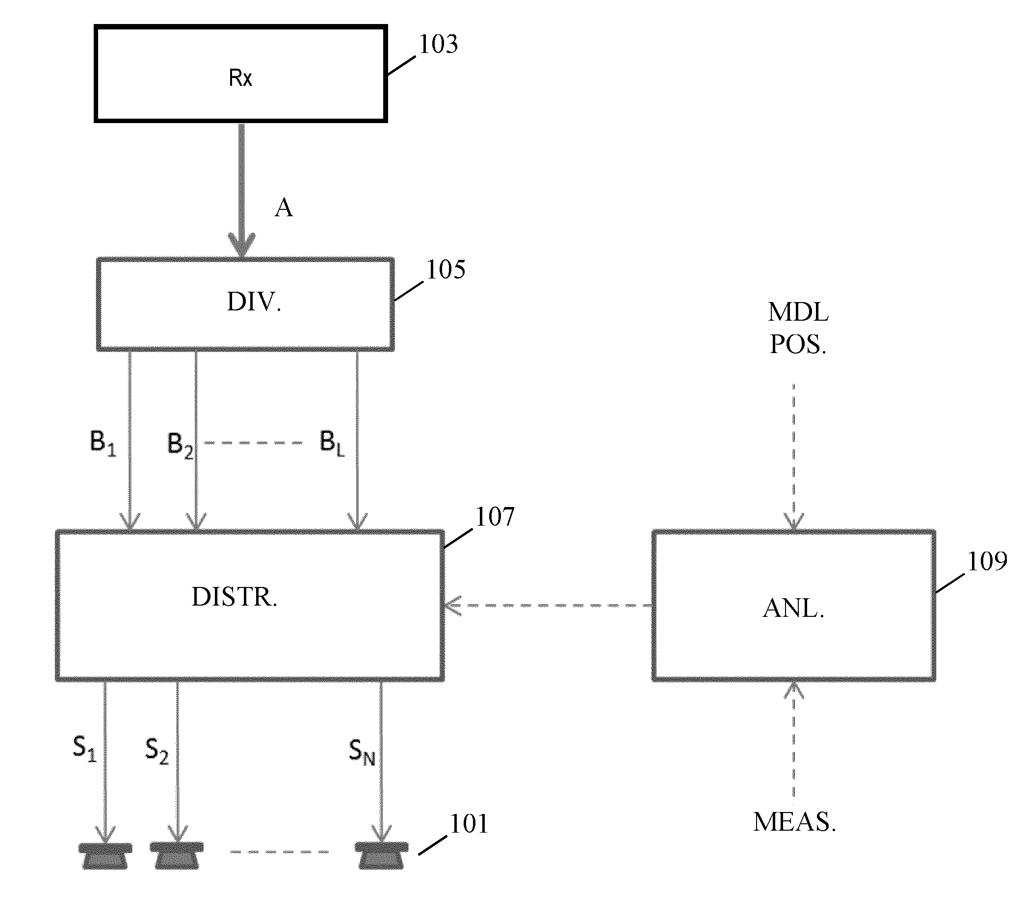
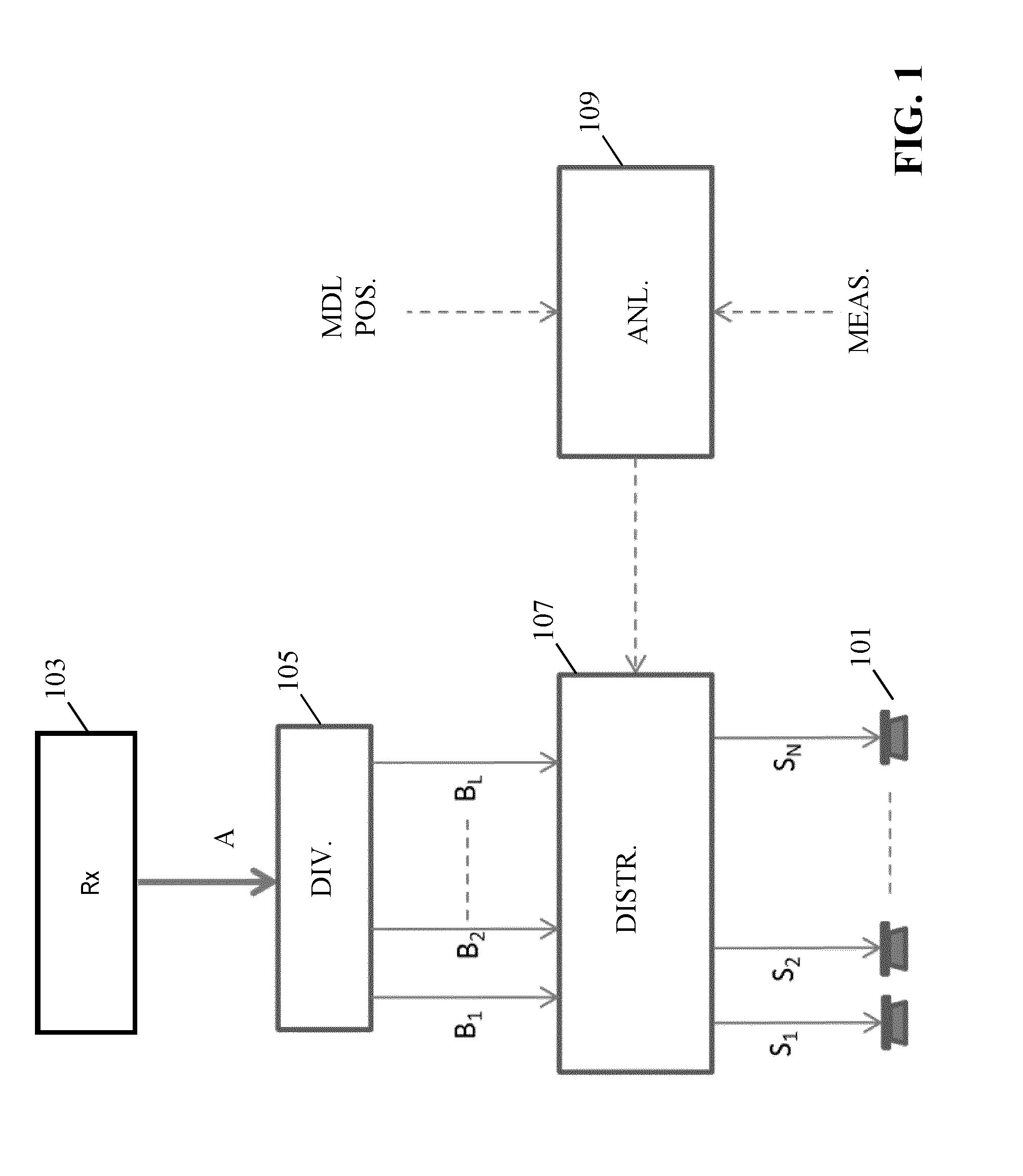
[0064]FIG. 1 illustrates an example of an audio apparatus for generating drive signals S1-SN for a plurality of speakers 101.

[0065]The drive signals S1-SN are generated from an input audio signal. The following description will for clarity and conciseness focus on the input audio signal being a single audio signal which is not associated with any specific position. However, it will be appreciated that the audio signal may for example be a component / single channel signal of a spatial multi-channel signal such as a 5.1 or 7.1 surround sound signal.

[0066]In the example, the loudspeakers 101 may for example be loudspeakers of a surround sound setup and the audio signal which is processed may be a low frequency signal, such as a Low Frequency Effect (LFE) channel. Thus, the following descrip...


PUM


Abstract

An audio apparatus generates drive signals for a plurality of loudspeakers (101) and comprises a receiver (103) for receiving an audio signal. A divider (105) divides typically a low frequency part of the audio signal into a plurality of audio subbands thereby providing a subband signal for each audio subband of the audio subbands. An analyzer (109) generates acoustic room response indications for each loudspeaker (101) for at least one subband. The indications may be indicative of a coupling of the individual loudspeaker to any room resonances in the individual subbands. A generator (107) generates the drive signals from the subband signals with the generator (107) being arranged to distribute at least a first subband signal of a first subband to the drive signals in response to the acoustic room response indications for the first subband. The analyzer (109) is being arranged to generate a first acoustic room response indication for a first loudspeaker (101) of the plurality of loudspeakers (101) and the first subband in response to a determination of a coupling of the first loudspeaker to at least one room resonance of an acoustic environment for the first loudspeaker (101). The apparatus may mitigate or reduce audio distortions caused by excitation of room resonances in a room.

Description

FIELD OF THE INVENTION[0001]The invention relates to a method and apparatus for generating drive signals for loudspeakers, and in particular, but not exclusively, for generating low frequency drive signals.BACKGROUND OF THE INVENTION[0002]Audio reproduction and rendering is continually developing towards being able to provide increasingly desirable audio experiences. This has resulted in an increasing complexity, flexibility and capability of the offered solutions. In particular, the desire to provide an enveloping and immerging experience to listeners has led to an increased focus on the provision of spatial audio. This has in particular led to rendering systems using a relatively high number of loudspeakers at positions distributed around the listening position. For example, surround sound systems using for example a 5.1 or 7.1 loudspeaker setup have become common in the consumer segment.[0003]However, a common problem with sound reproduction, particularly in small- to mid-sized s...

Claims


Application Information

Patent Timeline
Patent Type & Authority Applications(United States)
IPC IPC(8): H04S7/00
CPCH04S7/301H04S7/307H04S2400/07
Inventor DE BRUIJN, WERNER PAULUS JOSEPHUS
Owner KONINKLJIJKE PHILIPS NV
Why Eureka
Try Eureka