Transverse waveguide

a waveguide and waveguide technology, applied in the direction of transducer details, electrical transducers, electrical apparatus casings/cabinets/drawers, etc., can solve the problems of high acoustic loading of conical horns, insufficient bass of horns, and inability to produce adequate bass, so as to reduce noise and out-of-phase sound, reduce noise, and heat dissipation

Inactive Publication Date: 2011-11-29
BROMER NICHOLAS SHEPPARD
View PDF15 Cites 22 Cited by
  • Summary
  • Abstract
  • Description
  • Claims
  • Application Information

AI Technical Summary

Benefits of technology

[0025]Since filing the '376 Application, structures to enclose the back end of the speaker have been incorporated to reduce a buffeting that was noted and to reduce noise and out-of-phase sound from the back side of the speaker cone. The 24-inch, two-speaker version was the first, using two stainless steel salad bowls to cover the backs of the speakers. In latter versions, the back of the speaker cone was enclosed in a cabinet built onto the side of the transverse waveguide. The YouTube video (http: / / www.youtube.com / watch?v=YSaIkG_wGoQ) shows such a cabinet. A portion of the speaker's magnet structure protrudes through the side of this cabinet to allow the speaker to dissipate heat.
[0026]The invention includes the combination of a loudspeaker, waveguide, and cabinet where the cabinet includes a conventional resonance port. Adding a resonance port would limit the pressure inside the cabinet due to the motion of the rear of the speaker cone, and also would tend to limit the speaker cone excursion, which can damage the speaker if allowed to become too great. The resonance port can also augment the bass response at certain frequencies.
[0027]It has been found that when the back of the speaker protrudes from the side of the cabinet opposite to the waveguide, speakers with ventilation holes in the rear can create noise as the speaker is driven at high amplitude, due to air rushing in and out of the ventilation holes. To lessen such noise, a preferably vertical channel over the vent holes, perhaps lined with foam or other sound-absorbing material, can be used to dampen the air sound.

Problems solved by technology

A white paper on the Peavey Quadratic-Throat Waveguide (http: / / aa.peavey.com) states, “The weakness of conical horns lies in their acoustical loading characteristics for the transducer, which is insufficient at the low-frequency end.” (Contrary to this teaching, the inventors have demonstrated that a conical horn can exhibit high acoustical loading at bass frequencies.)
The company claims frequencies from 300 Hz to 20 kHz for the horn, and provides a 15-inch subwoofer in the same cabinet as the horn, which demonstrates that the horn does not produce adequate bass.
However, the prior artisans have not utilized this observation to produce bass, because of what is believed to be a misguided theory.
Yorkville's placement of the larger drivers close to the apex, and the failure to truncate the cone immediately below the larger drivers, are inefficient in generating bass, for the reasons set out below.
Like the Peavey design, the Yorkville design apparently includes space in the apex of the cone beyond the midrange speakers, which increases the length of the waveguide and also decreases the bass radiating efficiency.
The problem with existing combinations of radial horns and drivers is that their designs do not mimic the action of a large spherical or plane radiator, which are the known models for efficient radiation of bass sound, and therefore cannot generate bass sound efficiently.

Method used


Image

  • Transverse waveguide
  • Transverse waveguide
  • Transverse waveguide

Examples


Embodiment Construction

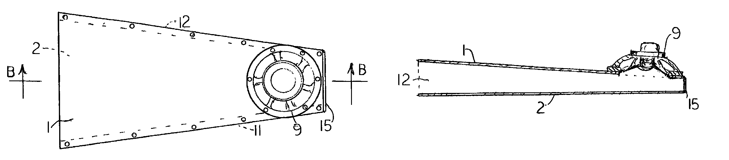
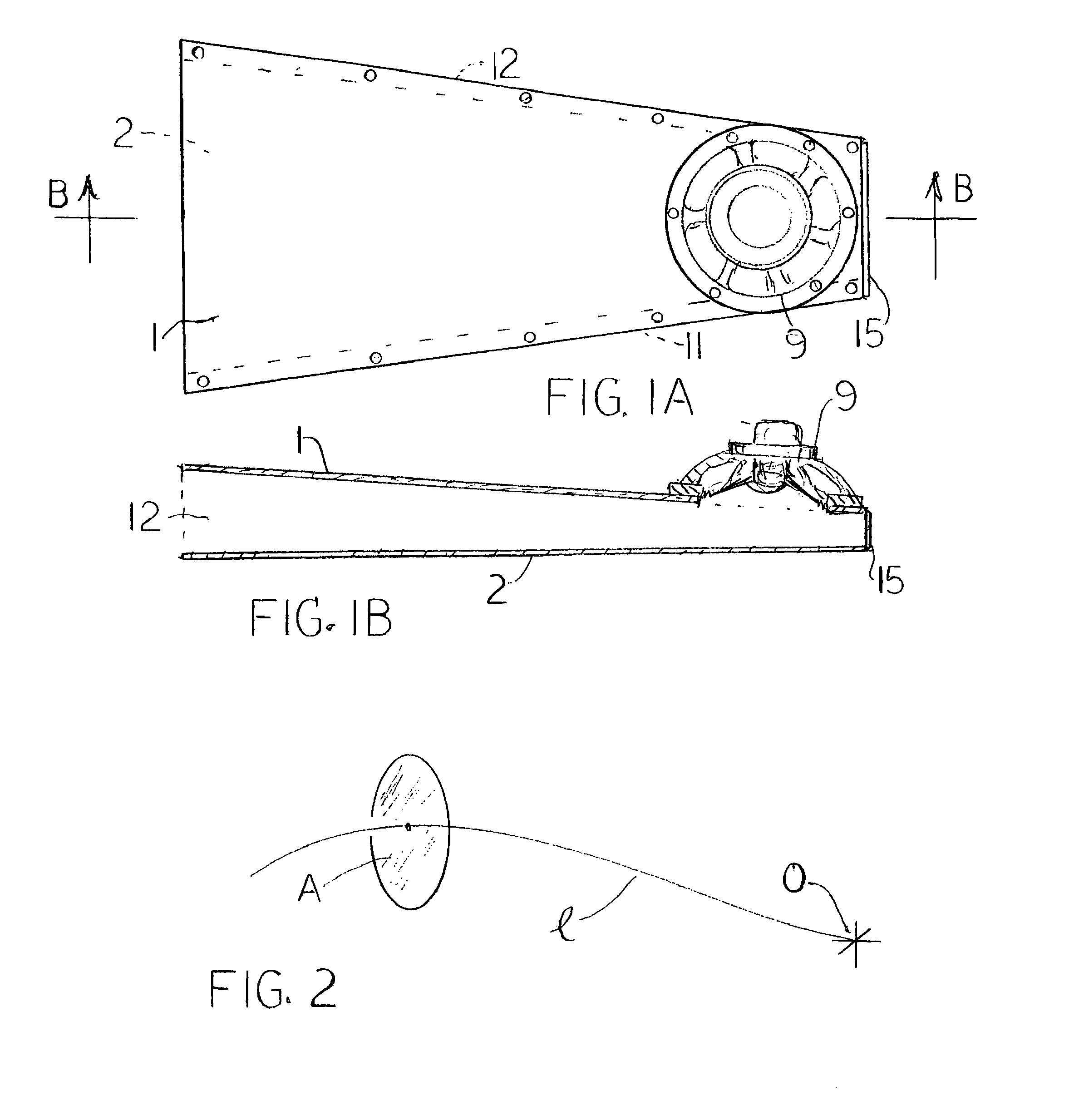
[0035]FIGS. 1A and 1B show an example of the invention. The exemplary illustrated cabinet comprises five pieces of wood: an upper plate 1 of, e.g., quarter-inch-thick “Baltic birch” plywood; a similar lower plate 2 that is congruent to the upper plate 1; a left-side piece of, e.g., ¾-inch thick pine board, 11, located between the plates 1 and 2 and immediately adjacent to side edges of the plates; a similar right-side board 12 that is congruent to the board 11 and is similarly placed on the other side of the cabinet; and an end plate 15. All of these optionally wooden parts can be fastened together with glue and / or screws. In the upper plate 1, but not in the lower plate 2, is an un-numbered generally round hole to accommodate a loudspeaker 9, which is placed and fastened over the hole. The loudspeaker axis is transverse to the widest dimensions of the waveguide, which is the reason for the name “transverse waveguide.” This configuration greatly reduces the size. Recently, woofers h...


PUM


Abstract

A compact bass speaker cabinet uses a long, narrow, tapered waveguide that acts as does a small radial portion of the air outside a large pulsating sphere, and has the same bass response as the large pulsating sphere. The smaller end is closed and the longer end is open. In one embodiment the inside of the waveguide is a rectangle about an inch thick and substantially as wide as the speaker or speakers that are mounted on the wider surface close to or slightly overlapping the closed end; and the inside surfaces are tapered so that they meet at a point which lies beyond the closed end by a distance equal to the radian wavelength of the longest sound wave that is to be produced.

Description

CROSS-REFERENCE TO RELATED APPLICATION[0001]This application claims the benefit of the provisional application entitled Sphere-Like Speaker Cabinet, Ser. No. 61 / 277,376, filed on Sep. 24, 2009 (the entire contents of which are entirely incorporated herein by reference).BACKGROUND OF THE INVENTION[0002]A source of sound and / or non-sound air motion (such as a loudspeaker) has been coupled to various hollow devices usually called horns or waveguides. These have been used to direct sound and also in attempts to generate low-frequency sound.[0003]One type of waveguide associated with generation of low-frequency sound is the “exponential” horn or waveguide. The name refers to the cross-sectional area (the area of a plane taken across the length of the horn), which increases exponentially with distance from the small end. In such horns the speaker is mounted, usually coaxially, at the smaller end. An exponential horn has no zero or convergence point at which the diameter reaches zero (corr...

Claims


Application Information

Patent Timeline
Patent Type & Authority Patents(United States)
IPC IPC(8): H05K5/00
CPCH04R1/2842H04R1/2857
Inventor BROMER, NICHOLAS SHEPPARD
Owner BROMER NICHOLAS SHEPPARD
Why Eureka
Try Eureka