
Method and apparatus for a cloth heater

a heater and cloth technology, applied in the field of cloth heaters, can solve the problems of indirect and inefficient heating methods, complicated use, and the majority of the parts of towels that cannot be heated,

Active Publication Date: 2006-03-09
ENGINEERED GLASS PRODS
View PDF24 Cites 33 Cited by
  • Summary
  • Abstract
  • Description
  • Claims
  • Application Information

AI Technical Summary

Benefits of technology

"The present invention is a method and apparatus for heating cloth using a heated panel with at least two major surfaces and a support member that physically supports the panel. The heated panel is placed on a horizontally disposed surface, and a cloth is placed across the surface. The heated panel heats the cloth at both major surfaces. The technical effect of this invention is that it provides a convenient and efficient way to heat cloth using a heated panel."

Problems solved by technology

Since cloth is not a good conductor of heat, only those portions of the towels that are in the direct line of irradiation from the glass are heated, thus most parts of the towels go unheated.
Although the above-mentioned cloth heaters do provide means to heat cloths, the heating means utilized are indirect and inefficient, may be somewhat complicated to use, in some cases require an enclosure, may require continuous high voltage, require much time to get the cloth to a heated condition, do not provide adequate temperature controls, do not heat large portions of a cloth, are costly, require a large footprint, pose a potential for burns and fire, require pumps and fluids that are noisy and potentially dangerous, require exposed electrical cords that are unsightly and may be dangerous, and whose overall appearance may not be aesthetically pleasing.

Method used


Image

  • Method and apparatus for a cloth heater
  • Method and apparatus for a cloth heater
  • Method and apparatus for a cloth heater

Examples


Embodiment Construction

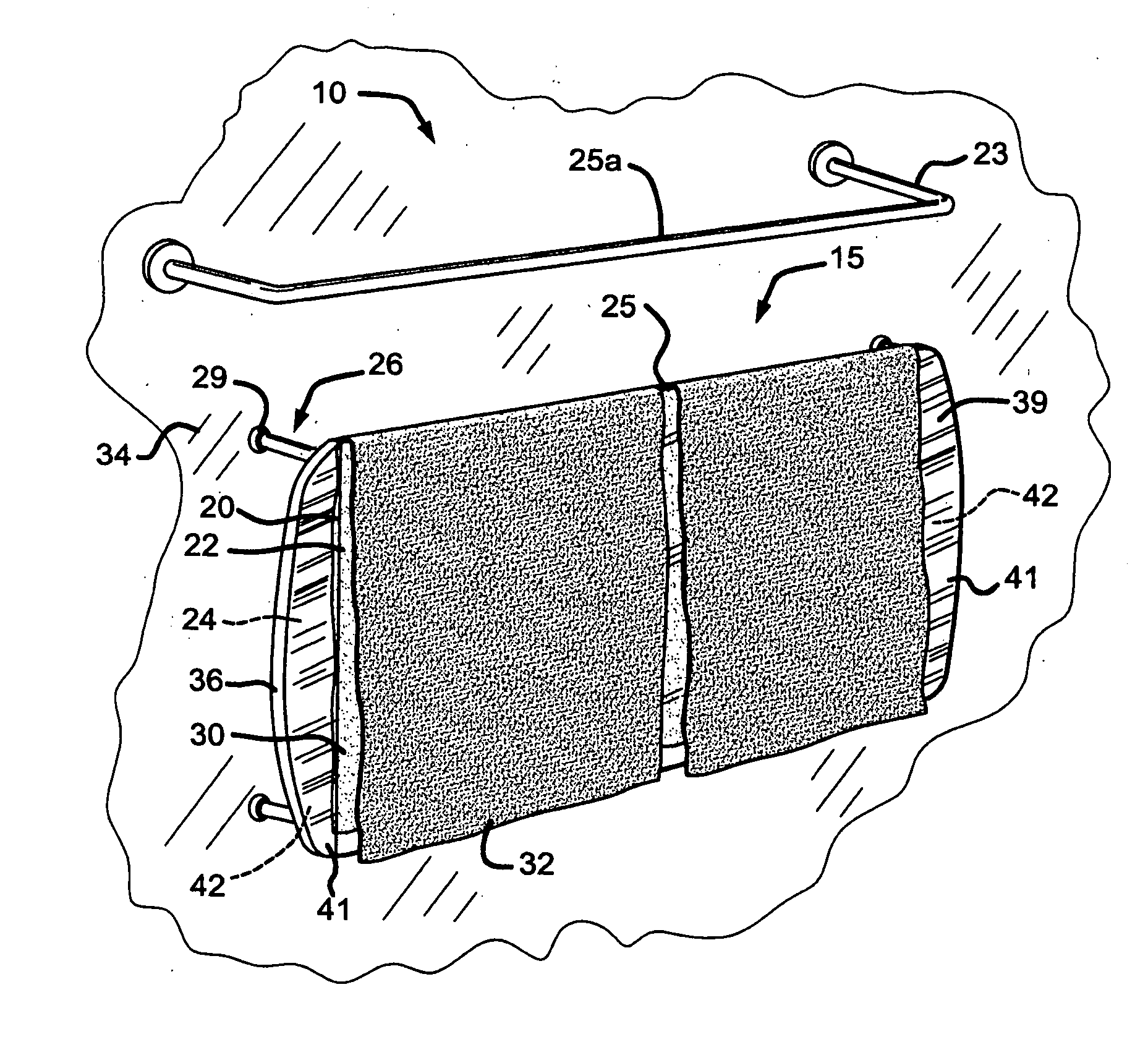
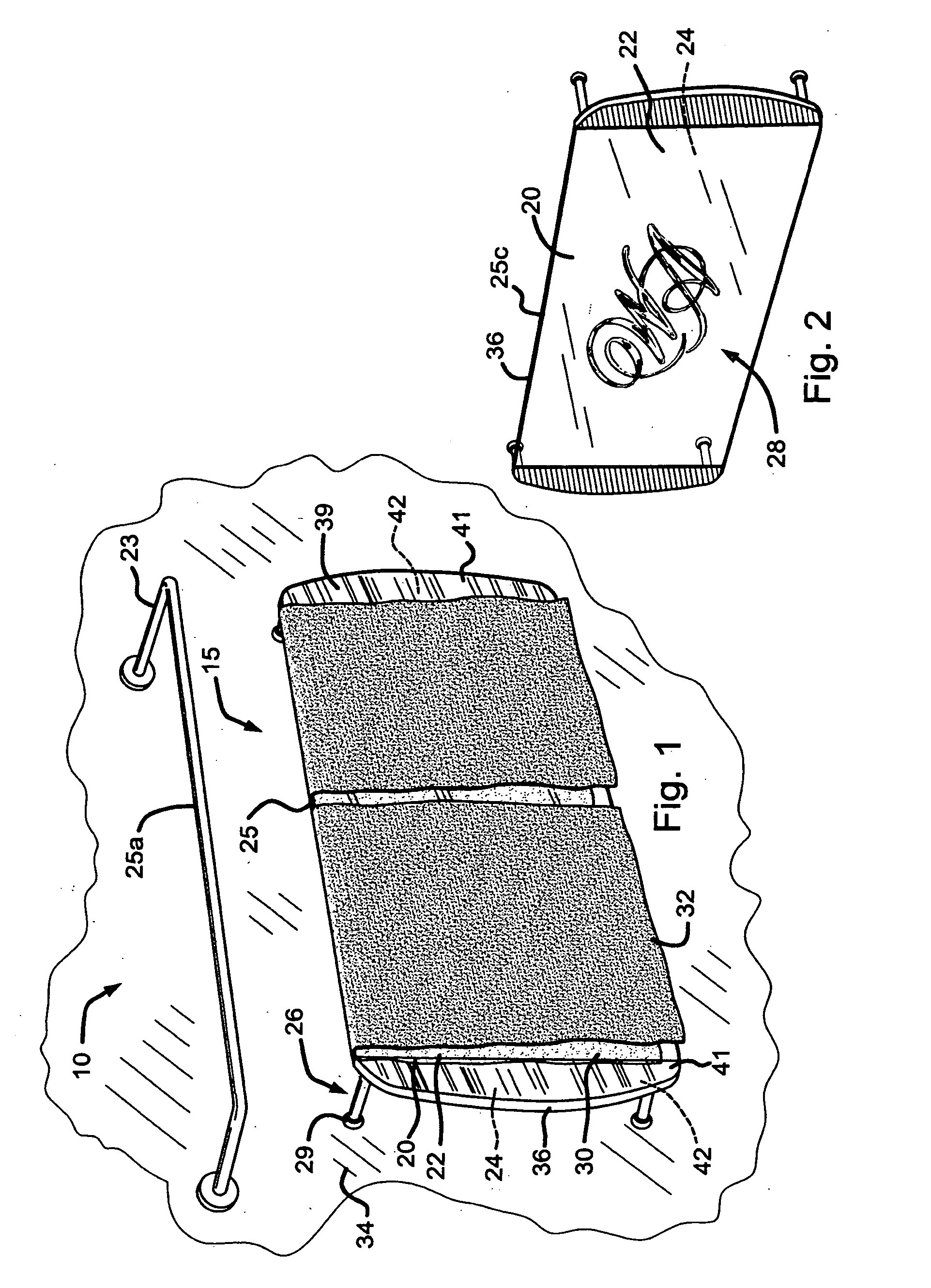
[0022] Referring to FIG. 1, a three dimensional front view of a preferred embodiment of a cloth heater 10 of the present invention is shown as having at least one heated panel 15 that has at least a first sheet of dielectric material 20. The panel 15 is depicted as substantially rectangular with rounded-edges, however, any geometric shape having any number of sides, including oval, circular, and heart shaped designs, are well within the spirit and scope of the present invention.

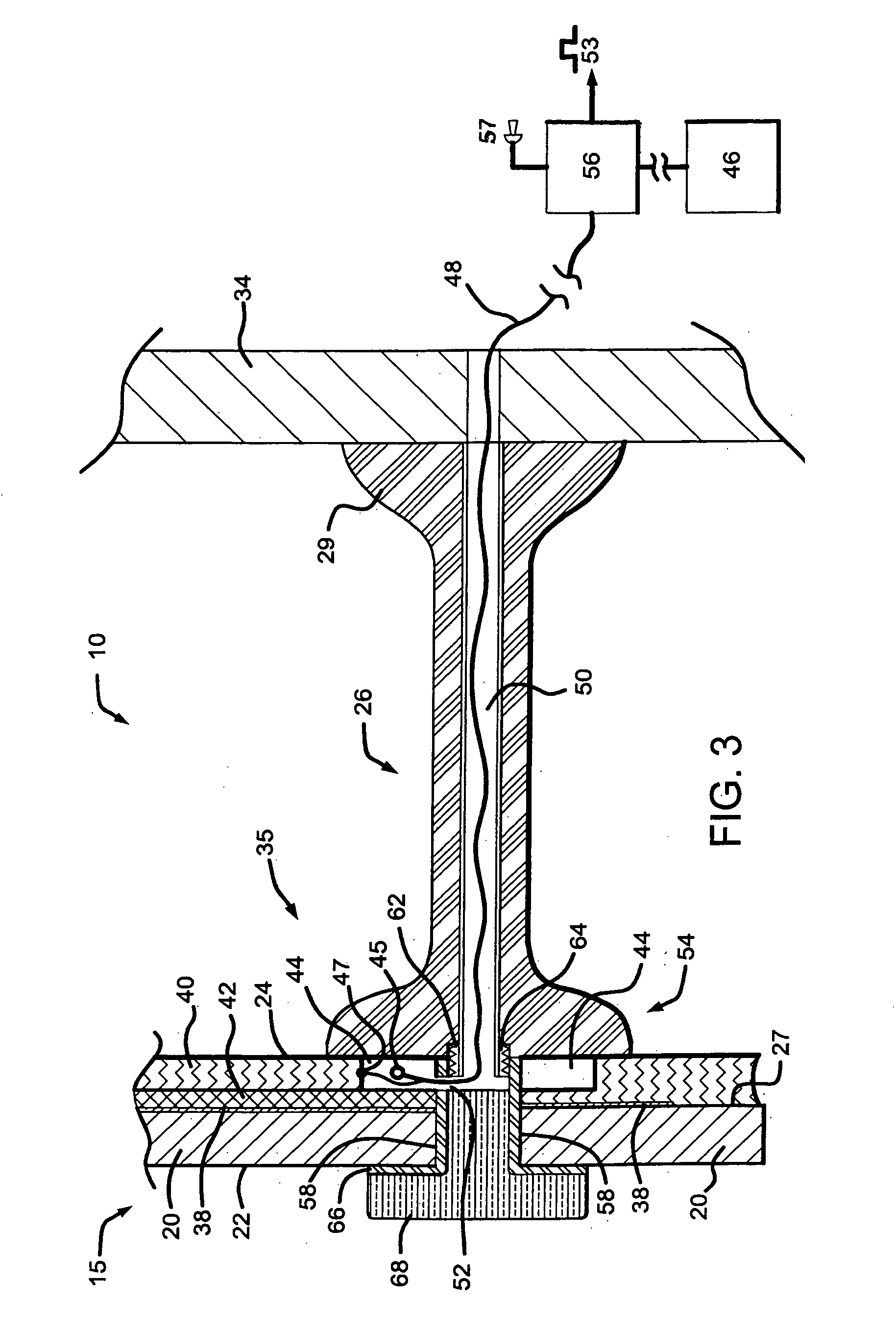
[0023] The first sheet 20 has a first major surface 22, and the panel 15 has an opposing second major surface 24. The first major surface 22 and the second major surface 24 are depicted as substantially planar, however, the cloth heater 10 can also have non-planar surfaces 22, 24. In this preferred embodiment, four support members 26 are utilized to mount the heated panel 15 to a wall 34.

[0024] As shown in FIG. 1, the support members 26 are straight and horizontally disposed. However, as FIGS. 1, 5, 10, and...


PUM


Abstract

A cloth heater and method for using the heater are provided. The heater utilizes a horizontally disposed surface, a heated glass panel, and support members. The horizontally disposed surface may comprise the top edge or surface of the heated glass panel, or a surface on a separate rack that is above and vertically inline with the top edge of the heated glass panel. The heated glass panel also has two opposing major surfaces. The support members physically support the heated glass panel and have electrical leads that communicate electrical power to the heated glass panel, thus heating the heated glass panel. When a cloth is placed across the horizontally disposed surface, the horizontally disposed surface supports the cloth, and the cloth makes contact with the two opposing major surfaces of the heated glass panel, thus heating the cloth at both opposing major surfaces.

Description

BACKGROUND OF THE INVENTION [0001] The present invention generally relates to a cloth heater and, more particularly, to a method and apparatus utilizing a heated panel for heating a cloth. BACKGROUND OF THE INVENTION [0002] In the past, hotels and motels have provided their customers with warm towels after, for example, showers or baths. For at least this purpose, hotels and motels have installed towel warmers for their customers. Now residences are being equipped with towel warmers, since residents also enjoy warmed towels. [0003] Over the years, towel warming devices have been developed utilizing a variety of different warming techniques. For example, U.S. Patent No. 4,117,309 to Cayley teaches an electric towel warmer having a conventional electrical heating element that is M-shaped and mounted to a frame within a housing. The conventional heating element radiates heat to an aluminum cover plate that has holes therethrough. When a towel is placed within Cayley's housing and over ...

Claims


Application Information

Patent Timeline
Patent Type & Authority Applications(United States)
IPC IPC(8): H05B3/20
CPCA47K10/06Y02B30/26F24D13/022Y02B30/00
Inventor GERHARDINGER, PETER F.ASHTON, DILLON R.
Owner ENGINEERED GLASS PRODS
Learn More