Method and system for forming shaped glass articles

a technology of shaped glass and machining method, which is applied in the direction of glass tempering apparatus, manufacturing tools, instruments, etc., can solve the problems of increasing cost, increasing the difficulty of difficult to remove total machining marks with polishing, so as to reduce the life of shaped glass articles, avoid undesirable pitting and staining of the flat area of the glass surface, and reduce the cost

Active Publication Date: 2014-08-21
CORNING INC
View PDF25 Cites 90 Cited by
  • Summary
  • Abstract
  • Description
  • Claims
  • Application Information

AI Technical Summary

Benefits of technology

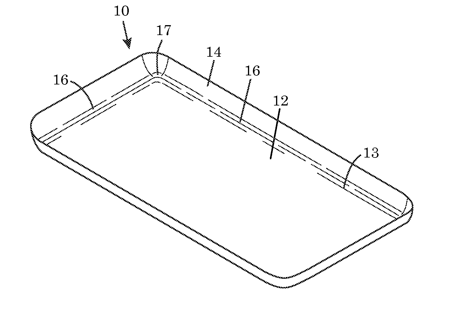
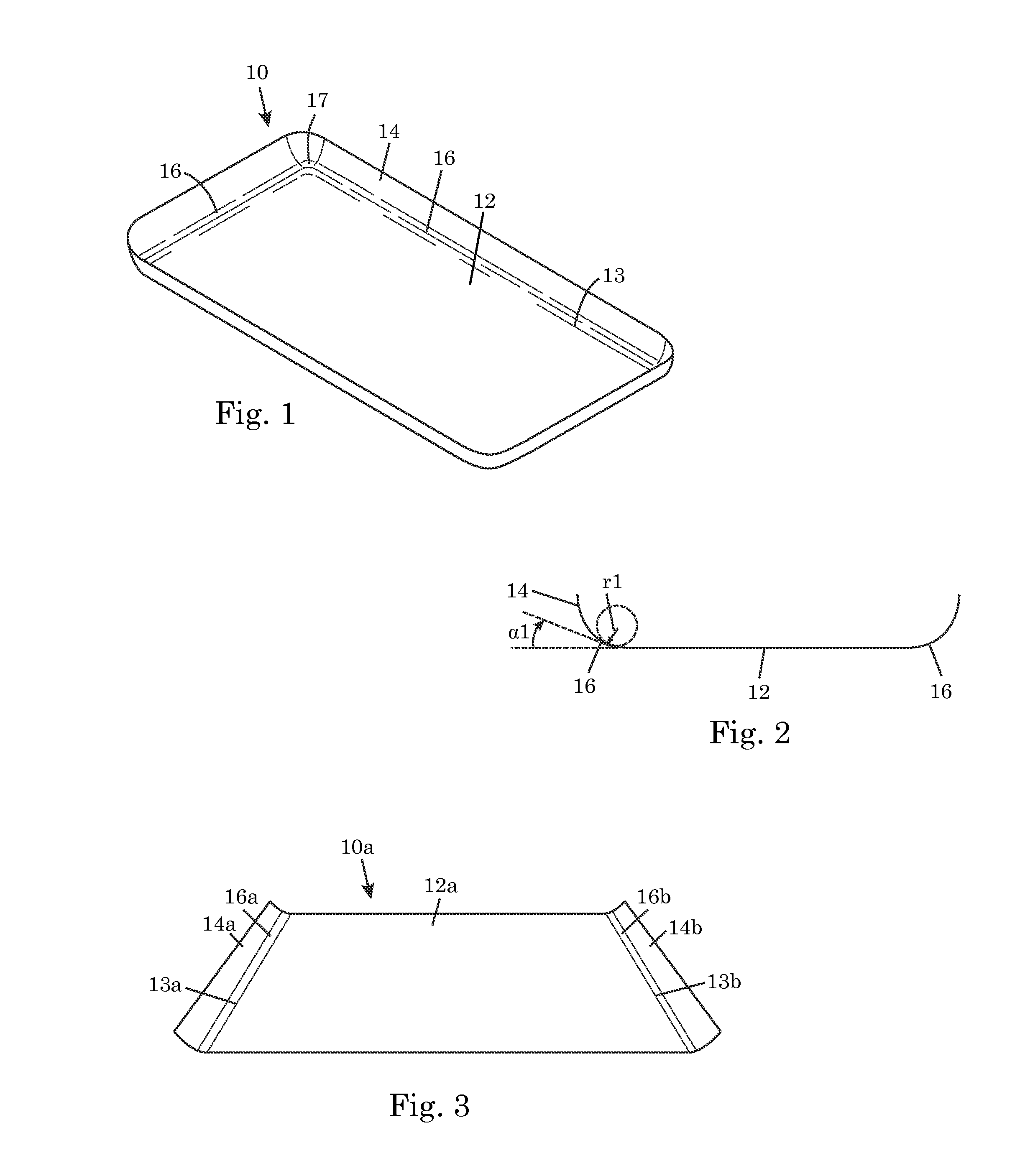
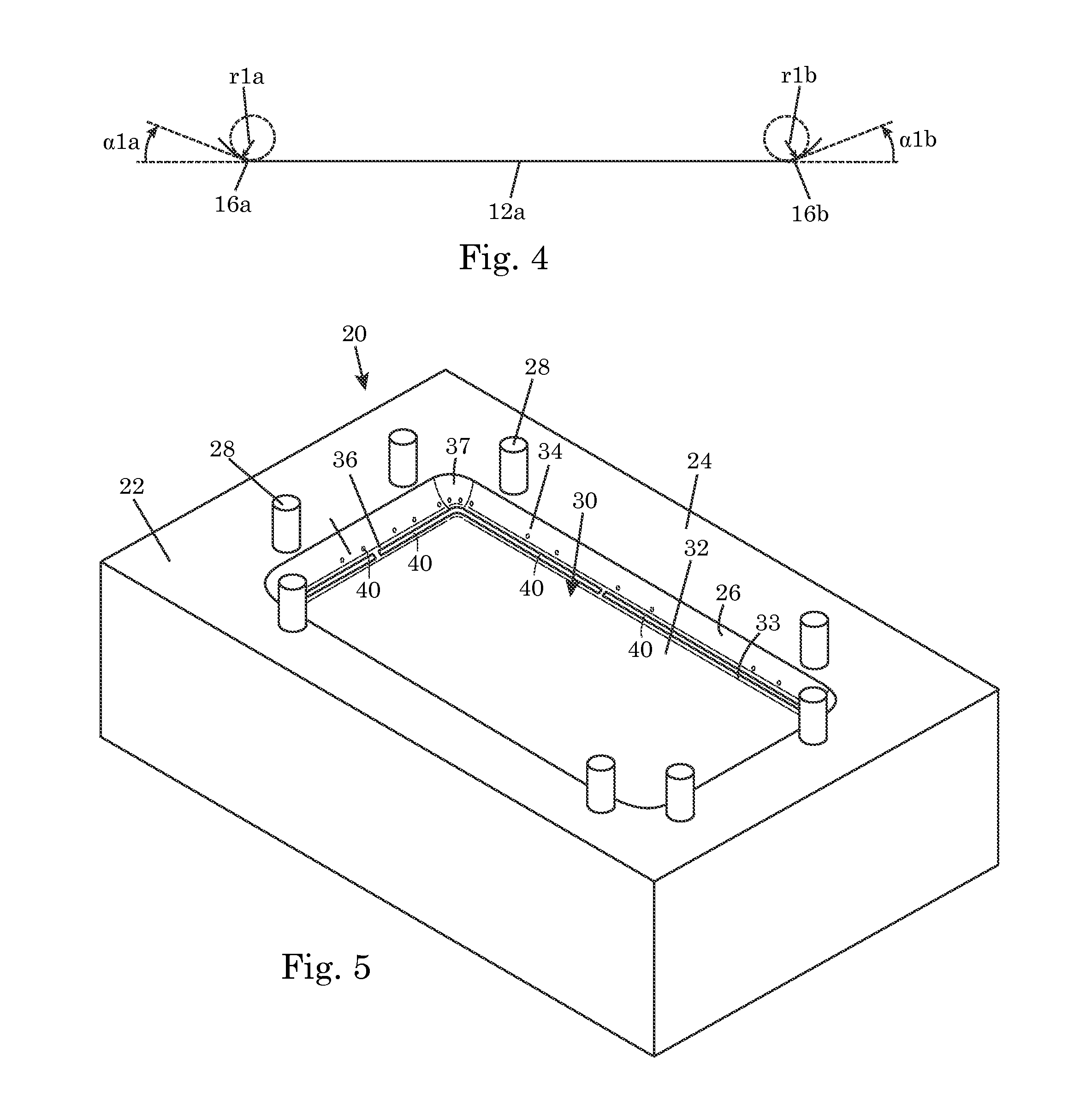
[0009]According to the present disclosure, it is desirable to keep the flat area of the mold colder than the bend area of the mold during the bend forming process. It is also desirable to get the glass sheet and mold locally hot in the bend area so that bends and corners can be precisely formed in the glass sheet. It is further desirable to keep the glass sheet and mold relatively cold in the flat area while the glass sheet and mold are hot in the bend area so that undesirable pitting and staining in the flat area of the glass surface can be avoided.

Problems solved by technology

Shaped glass articles with small radius bends and corners are difficult and expensive to make using glass machining.
Glass machining involves large material removal, which greatly increases cost.
Total removal of machining marks with polishing is difficult to impossible.
It is also very difficult to achieve an even polish on curved sections without inducing optical distortions in the glass article.
However, there are also challenges with precision forming of small radius bends and corners with this approach, especially when the glass has a high softening point and requires relatively high temperatures to form the bends and corners.
If the flat area of the glass sheet is below 109.9 poise or the flat area of the mold is at the same temperature as the bend area of the mold during the long contact between the flat area of the glass sheet and the flat area of the mold, the glass surface may have undesirable pitting and staining in the flat area due to interaction with the mold.
The mold life will also be shortened if the glass is in contact with the mold at a relatively high temperature for a relatively long period.

Method used


Image

  • Method and system for forming shaped glass articles
  • Method and system for forming shaped glass articles
  • Method and system for forming shaped glass articles

Examples


example 1

[0096]A shaped glass article was formed using a mold with a dish-shaped mold cavity. The forming process included local heating of the bend area without active cooling of the mold surface flat area. Various profiles characterizing the process are shown in FIG. 12. The thermal profile at the center of the mold surface flat area is shown at 100. The thermal profile at a bend on the mold surface curved area is shown at 102. The thermal profile at a corner on the mold surface curved area is shown at 104. The vacuum profile is shown at 106. The furnace power profile is shown at 108. The furnace temperature profile is shown at 110. The time at which the furnace was opened is indicated at 112. The temperature difference between the mold surface flat area (represented by thermal profile 100) and the mold surface curved area (represented by thermal profile 102 or 104) is relatively small. The temperature difference between the mold surface flat area and the mold surface curve area peaks at a...

example 2

[0097]A shaped glass article was formed using a mold with a dish-shaped mold cavity. The forming process include local heating of the bend area with active cooling of the mold surface flat area. Various profiles characterizing the process are shown in FIG. 13. The thermal profile at the center of the mold surface flat area is shown at 114. The thermal profile at a point on the mold surface curve area is shown at 116. The thermal profile at the center of the glass flat section is shown at 118. The thermal profile at a point on the glass curved section is shown at 120. The vacuum profile is shown at 122. The furnace power profile is shown at 124. The furnace temperature profile is shown at 126. The active cooling profile is shown at 128. Nitrogen was used as the cooling fluid. The time at which the furnace was opened is indicated at 130. The temperature difference between the mold surface flat area (represented by thermal profile 114) and the mold surface curved area (represented by t...

example 3

[0098]Various dish-shaped glass articles were formed using a mold with a dish-shaped mold cavity. Local heating of the mold surface area and active cooling of the mold surface flat area were employed in the process. The glass articles were made from Code 2317 GORILLA® glass available from Corning Incorporated. The glass sheets used in making the glass articles had a thickness of 0.8 mm. The dish shape had a bend radius of 10 mm. The effect of mold corner temperature on corner deviation of the formed shape from the ideal shape was investigated by varying the temperature in the mold surface bend area. The results are shown in FIG. 14. In FIG. 14, the diamond markers 140 represent DOE (“design of experiments”) data and the square markers 141 represent the final process data. The data shows that increased mold bend temperature resulted in reduced deviation from ideal shape, thus demonstrating the importance of increasing edge and corner temperatures. For the particular glass composition...


PUM

PropertyMeasurementUnit
viscosityaaaaaaaaaa
viscosityaaaaaaaaaa
glass viscosityaaaaaaaaaa

Abstract

A method of forming a shaped glass article includes placing a glass sheet on a mold such that a first glass area of the glass sheet corresponds to a first mold surface area of the mold and a second glass area of the glass sheet corresponds to a second mold surface area of the mold. The first glass area and the second glass area are heated such that the viscosity of the second glass area is 8 poise or more lower than the viscosity of the first glass area. A force is applied to the glass sheet to conform the glass sheet to the mold surface. During the heating of the second glass area, the first mold surface area is locally cooled to induce a thermal gradient on the mold.

Description

[0001]This application claims the benefit of priority under 35 U.S.C. §119 of U.S. Provisional Application Ser. No. 61 / 766,878 filed on Feb. 20, 2013 the content of which is relied upon and incorporated herein by reference in its entirety.FIELD[0002]The present disclosure relates to production of shaped glass articles usable as cover glass for electronic devices.BACKGROUND ART[0003]Industrial design is driving demand for shaped cover glass for portable electronic devices such as smart phones and tablets. A typical shaped cover glass of interest has a combination of a large flat section for covering the front side of the electronic device and one or more curved sections for wrapping around one or more edges of the electronic device. The curved sections include bends and corners where they intersect with the flat sections. A flat electronic device will require a small bend radius, e.g., less than 20 mm, to allow the curved section to wrap around an edge of the device while maintaining...

Claims


Application Information

Patent Timeline
Patent Type & Authority Applications(United States)
IPC IPC(8): C03B23/023G06F1/16
CPCG06F1/1626C03B23/0235C03B2225/02Y02P40/57Y10T428/24355Y10T428/24628C03B23/0357
Inventor IMMERMAN, JACOBKEEBLER, THOMAS A.SALTZER, JR., JOHN ROBERTUKRAINCZYK, LJERKA
Owner CORNING INC
Why Eureka
Try Eureka