Heating apparatus for liquefied gas fuel supply system

a technology of liquefied gas and heating apparatus, which is applied in the direction of mechanical equipment, engines, machines/engines, etc., can solve the problems of insufficient vaporization of fuel, insufficient energy utilization, and aspect of energy efficiency, so as to inhibit excessive vaporization and properly vaporize fuel

Inactive Publication Date: 2006-03-16
FUJITSU GENERAL LTD
View PDF3 Cites 33 Cited by
  • Summary
  • Abstract
  • Description
  • Claims
  • Application Information

AI Technical Summary

Benefits of technology

[0025] According to this structure, when the temperature of the engine cooling water in the internal-combustion engine is higher than the predetermined threshold value, the liquefied gas fuel is no longer heated, and thereby excessive vaporization is inhibited. The threshold value is changed depending on the vapor pressure characteristic of the liquefied gas fuel detected by the detecting unit, so that it is possible to more properly vaporize the fuel.

Problems solved by technology

Thus, for example, when an applied amount of heat is insufficient, there is a possibility that the fuel is insufficiently vaporized so as to have adverse influence on fuel injection control etc.
To the contrary, when an applied amount of heat is excessive, there is possibility that the fuel vaporized generates gas at excessive pressure, or the resulting energy is uselessly, which causes a problem in the aspect of energy efficiency.
In particular, when the heat of the engine cooling water can not be used in heating the fuel, for example when a cold engine is started, there is no alternative but to generate by the electric heater the whole quantity of heat required to heat the fuel.
This useless energy consumption is significant.
In this manner, the supply system of the liquefied gas fuel involves the problems set forth above due to the difference in component or temperature of the fuel.

Method used


Image

  • Heating apparatus for liquefied gas fuel supply system
  • Heating apparatus for liquefied gas fuel supply system
  • Heating apparatus for liquefied gas fuel supply system

Examples


Embodiment Construction

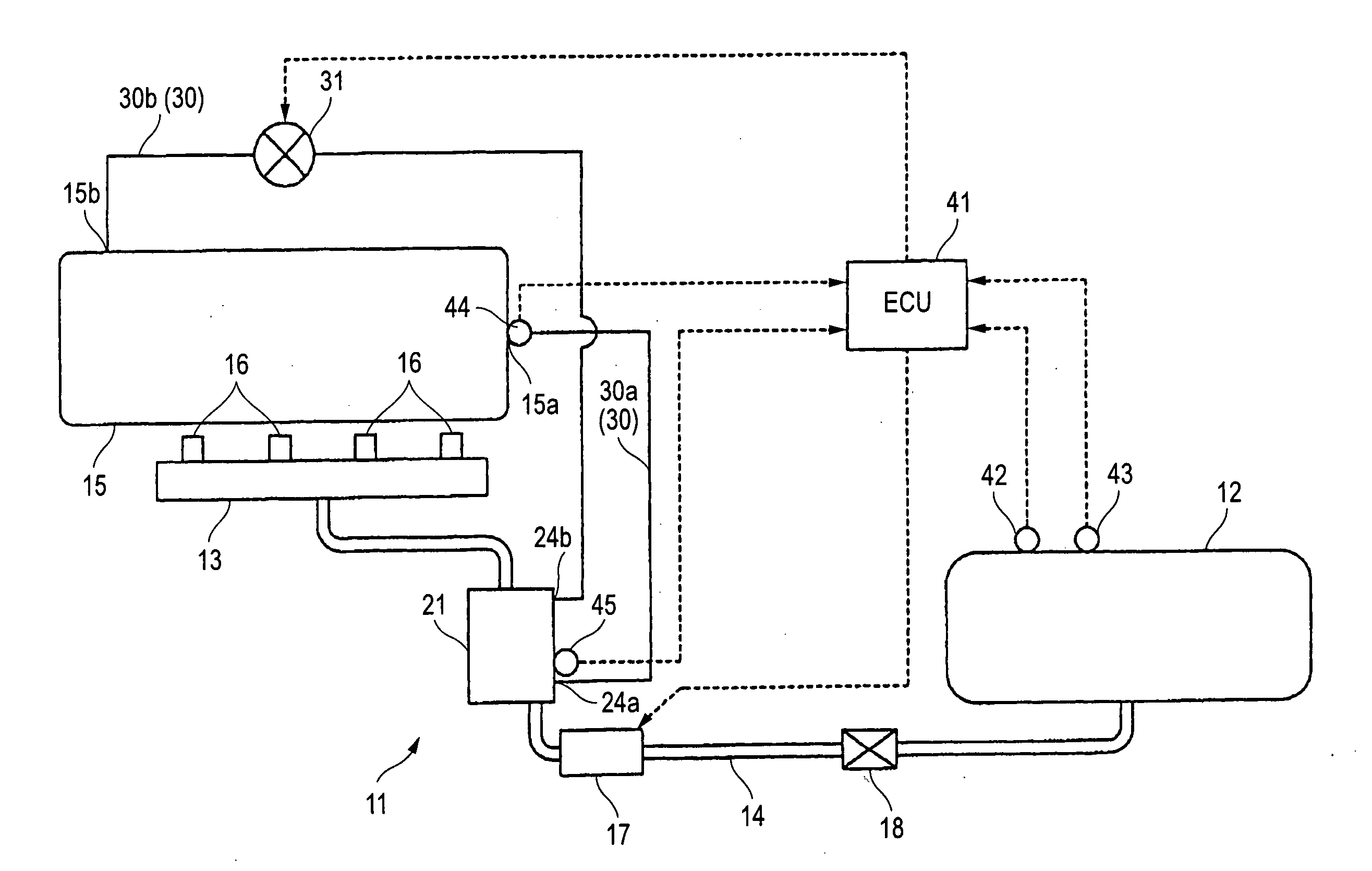
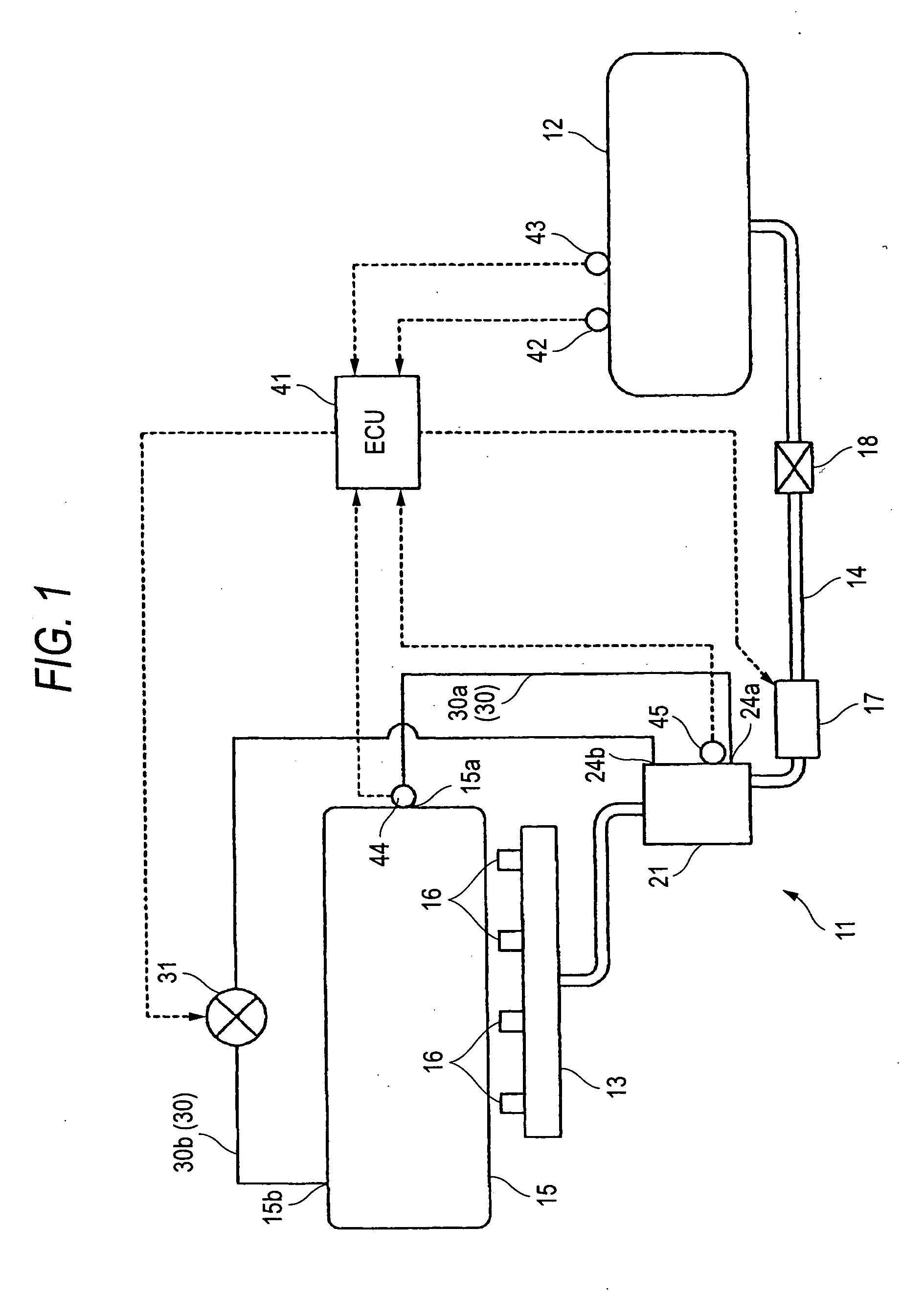
[0033] Hereinafter, a heating apparatus according to one embodiment of the invention in a liquefied gas fuel supply system of an internal-combustion engine for automobile use will be described with reference to FIGS. 1 to 7. Further, in the liquefied gas fuel supply system of this embodiment, liquefied petroleum gas (LPG) is supplied as a fuel to the internal-combustion engine.

[0034] As shown in FIG. 1, a liquefied gas fuel supply system 11 includes a fuel tank 12, a delivery pipe 13, and a fuel passage 14 that supplies fuel in the fuel tank 12 to the delivery pipe 13. The delivery pipe 13 is provided with a plurality of injectors 16 that inject the fuel into respective combustion chamber (not shown) of an internal-combustion engine 15. These injectors 16 are actually mounted on the internal-combustion engine 15. However, for the sake of convenience, these injectors 16 are shown to be separated from the internal-combustion engine 15 in the drawing.

[0035] The fuel is hermetically s...


PUM


Abstract

A heating apparatus for a liquefied gas fuel supply system includes a heating unit, a detecting unit and a setting unit. The liquefied gas fuel supply system vaporizes liquefied gas fuel to supply the vaporized gas fuel to an internal-combustion engine. The heating unit heats the liquefied gas fuel before the liquefied gas fuel is vaporized. The detecting unit detects vapor pressure characteristic of the liquefied gas fuel. The setting unit sets an amount of heat to be applied to the liquefied gas fuel on a basis of a detection result by the detecting unit.

Description

BACKGROUND OF THE INVENTION [0001] 1. Field of the Invention [0002] The present invention relates to a heating apparatus for a liquefied gas fuel supply system, for heating liquefied gas fuel when the fuel is vaporized to be supplied to an internal-combustion engine. [0003] 2. Description of the Related Art [0004] As well known, an internal-combustion engine, which is provided in, for example, an automobile using a liquefied gas fuel such as liquefied petroleum gas (LPG) is designed to vaporize in a vaporizer the fuel stored under a high pressure and to use the vaporized fuel for combustion. The vaporizer is cooled by latent heat of vaporization of the fuel. When the vaporizer is excessively cooled, the fuel undergoes insufficient vaporization, which has adverse influence on fuel injection control, etc. [0005] Conventionally, in order to prevent such an excessive cooling, JP 2003-328859 A discloses a system for heating fuel in which a heating apparatus introduces engine cooling wate...

Claims


Application Information

Patent Timeline
Patent Type & Authority Applications(United States)
IPC IPC(8): F02M21/06
CPCF02M21/06Y02T10/32F02M21/0239F02M21/0212F02D19/027F02D19/029F02D19/022Y02T10/30
Inventor HAYASHI, KENJIKOMODA, TAKAOTORII, MASANORISAIKI, TOSHINARIKOSAKA, MASAYUKITAGUCHI, TOSHIMITSU
Owner FUJITSU GENERAL LTD
Why Eureka
Try Eureka