Instrumented plunger for an oil or gas well

a technology for oil or gas wells and plungers, which is applied in the direction of fluid removal, survey, borehole/well accessories, etc., can solve the problems of reducing the ability of wells to maintain the pressure necessary to continuously pump oil and/or gas, reducing the economic value of capping wells, and reducing the flow rate of data, etc., to achieve the effect of facilitating data flow

Active Publication Date: 2006-03-16
CHISHOLM CHRISTIAN
View PDF6 Cites 68 Cited by
  • Summary
  • Abstract
  • Description
  • Claims
  • Application Information

AI Technical Summary

Benefits of technology

[0018] In a second aspect of the present invention another plunger adapted for use with a well is described. The plunger comprises (1) a substantially cylindrical body, (2) at least one memory storage device, (3) at least one data controller, and (4) at least one data transfer device coupled with the at least one data controller. The at least one data controller is both coupled with the at least one memory storage device and adapted to manage the flow of data in and out of the at least one memory storage device. The at least one data transfer device is adapted to facilitate the flow of data between the plunger and an external device.

Problems solved by technology

As the well ages and more wells are placed into a common basin, the well's ability to maintain the pressure necessary to continuously pump oil and / or gas declines due to natural pressure depletion.
If a sufficient reserve of oil or gas remains in the reservoir, capping the well may not be economically desirable.
However, this can be a very expensive proposition not only requiring an operator to install a pumping system, but also to provide a source of power to run the pump.
As can be appreciated, many wells are located in remote locations where sources of energy are not easily or inexpensively recovered.
Typically, mechanical pump lift systems are only utilized on wells where the volume of the reserve accessible by the well is considerable enough to justify the expensive of fitting the well with the expensive pumping system and to justify the increased operational expenses.
Additionally, in this variation shutting a flow line valve will also cause the plunger to fall.
As can be appreciated, having to pull tubing to remove a stuck plunger from a well results in downtime that the well could otherwise be producing.
The build up of paraffin and other debris, especially around tubing collar joints, can build up over time and can eventually cause a plunger to become stuck.

Method used


Image

  • Instrumented plunger for an oil or gas well
  • Instrumented plunger for an oil or gas well
  • Instrumented plunger for an oil or gas well

Examples


Embodiment Construction

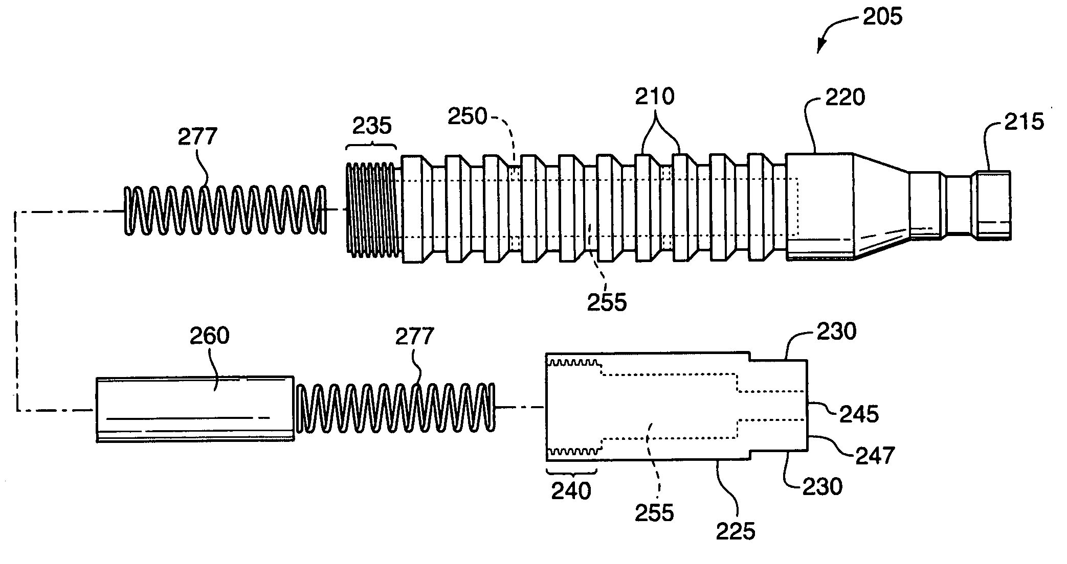
[0033] One embodiment of the present invention comprises a plunger used in the artificial lift of oil and gas wells that includes one or more sensor assemblies. The sensor assemblies are capable of monitoring and recording data about the conditions in the well's tubing string and / or casing such as, but not limited to, temperature, pressure, fluid type, acceleration, velocity, location and load on the plunger during its ascent and descent. The data can be monitored and recorded periodically or continuously throughout the cyclical operation of the plunger.

[0034] In preferred variations of the one embodiment, the data are transferred (or downloaded) to a controller or other data repository when the plunger is held in the lubricator / catcher in the christmas tree either through mechanical contacts or a wireless transmission means. In other variations, the sensor assembly is periodically removed from the body of the plunger, operatively coupled with a controller, computer or other device...


PUM


Abstract

In one embodiment of the present invention, a plunger for use in a plunger lift system of an oil or natural gas well is described. The plunger includes one or more sensor assemblies, each including one or more sensors for measuring various physical and operational conditions during the operation of the well. The data acquired from the sensors is stored in memory within the sensor assemblies and downloaded to the plunger lift system controller when the plunger is located in the catch/lubricator. The data can then be analyzed by the controller or other computer to vary the well's operating parameters to maximize the well's operating efficiency and the data can be used in reservoir management, such as transient testing, reservoir modeling and interference testing.

Description

FIELD OF THE INVENTION [0001] This invention generally relates to plunger lift systems used with oil and gas wells. More particularly, this invention pertains to a plunger including instrumentation or other electronics contained therein for acquiring data concerning one or both of the operation of the plunger and physical conditions in the well bore and reservoir. BACKGROUND [0002] When a well is first drilled and put into operation, the reservoir pressure in the well is generally sufficient to cause oil and / or gas contained in the well to rise to the surface where it is collected and stored. As the well ages and more wells are placed into a common basin, the well's ability to maintain the pressure necessary to continuously pump oil and / or gas declines due to natural pressure depletion. Once the reservoir pressure is no longer sufficient to permit continuous pumping, a well operator must either install an artificial lift system or cap the well. If a sufficient reserve of oil or gas ...

Claims


Application Information

Patent Timeline
Patent Type & Authority Applications(United States)
IPC IPC(8): E21B43/00
CPCE21B47/01E21B43/121
Inventor CHISHOLM, CHRISTIAN
Owner CHISHOLM CHRISTIAN
Why Eureka
Try Eureka