Piezoelectric actuator and micro-electromechanical device

a micro-electromechanical and actuator technology, applied in the field of actuators, can solve the problems of vertical warpage of beams, difficult control of residual stress in piezoelectric films, and difficult adjustment of capacitance values with an applied voltage to variable capacitors, etc., to suppress warpage and high accuracy. reproducibility

Inactive Publication Date: 2006-03-16
KK TOSHIBA
View PDF5 Cites 118 Cited by
  • Summary
  • Abstract
  • Description
  • Claims
  • Application Information

AI Technical Summary

Benefits of technology

[0015] It is an object of the present invention to provide a micro-electromechanical device having a piezoelectric actuator which is capable of controlling a displacement with high accuracy and reproducibility, by suppressing a warpage due to residual stress in a piezoelectric film.

Problems solved by technology

Therefore, it is a serious problem that the beam is vertically warped due to a slight residual stress in a material of the piezoelectric film.
Hence, it is extremely difficult to adjust a capacitance value with an applied voltage to a variable capacitor as designed, or to set a drive voltage of a switch at a steady value.
In the case of using a piezoelectric material having such a large inverse piezoelectric effect in order to increase the piezoelectric strain of the piezoelectric film of the piezoelectric actuator, it is difficult to control a residual stress in a piezoelectric film, and to suppress a warpage of the actuator.
In such piezoelectric material, a drive range of the actuator cannot be sufficiently increased in comparison with the warpage of the actuator.
Due to the problems as described above, technological application of the piezoelectric actuator is precluded.
The piezoelectric actuator is largely warped by the slight residual stress due to a serious problem relating to such a structure of the piezoelectric actuator, that is, the thin and long beam structure.
Therefore, it is difficult to fabricate a variable capacitor with a capacitance held constant, or a switch with an operation voltage held constant.

Method used


Image

  • Piezoelectric actuator and micro-electromechanical device
  • Piezoelectric actuator and micro-electromechanical device
  • Piezoelectric actuator and micro-electromechanical device

Examples


first modification

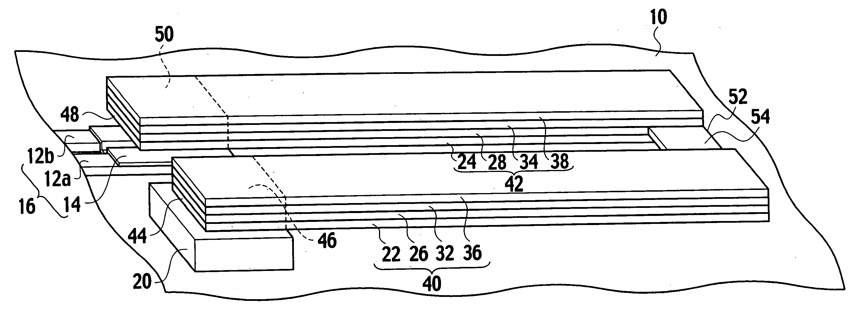
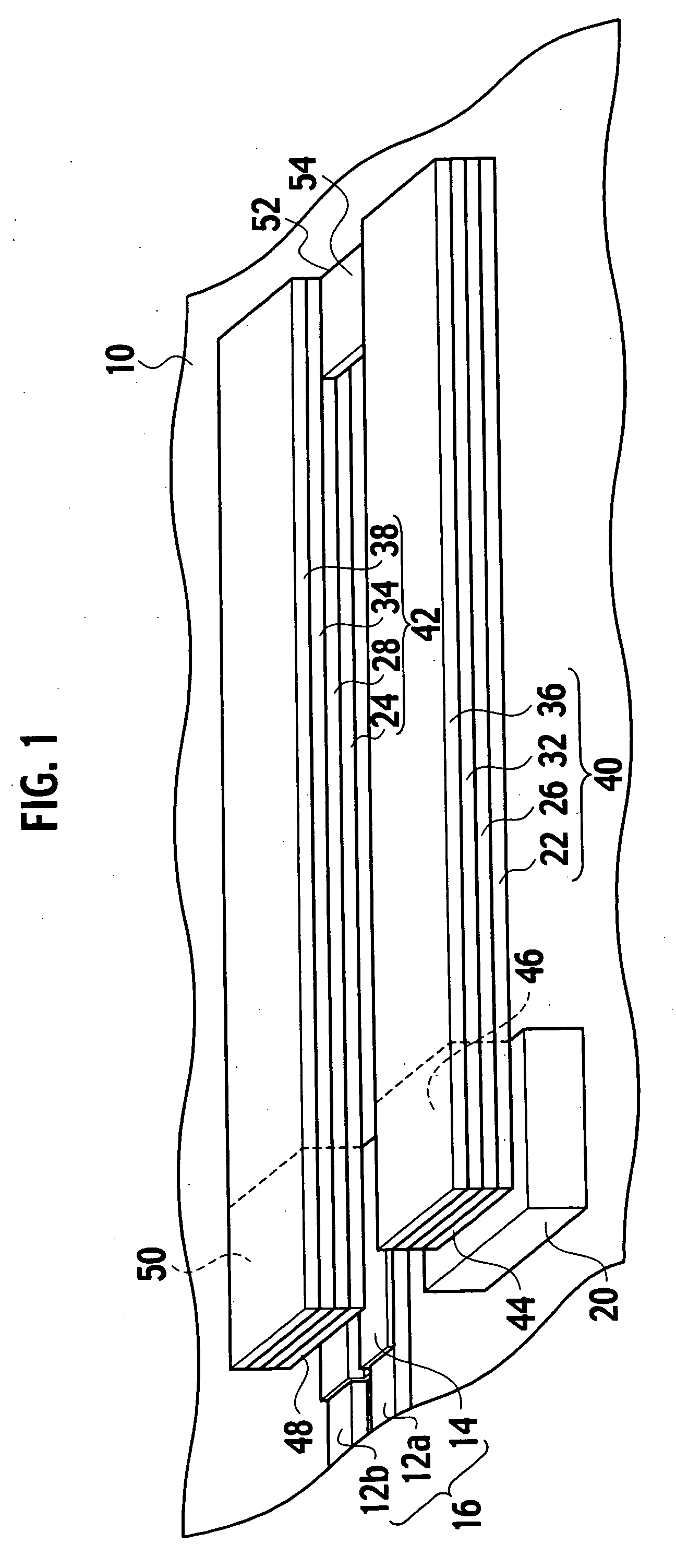
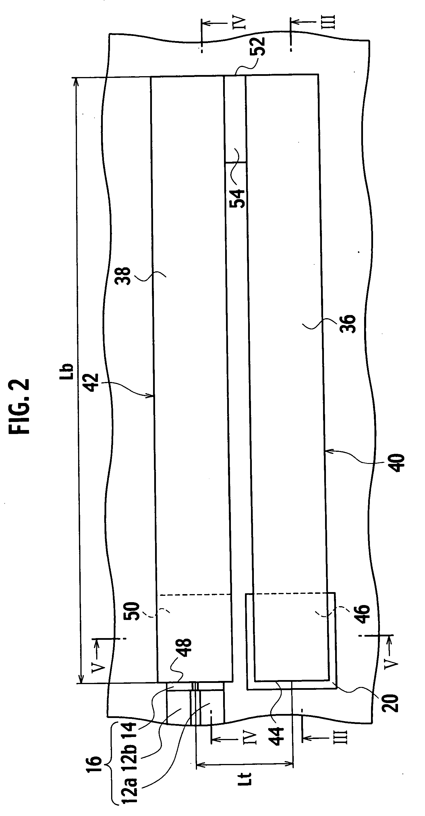
[0092] A piezoelectric actuator according to a first modification of the embodiment of the present invention, as shown in FIG. 18, includes a first beam 40, a second beam 42, and a third beam 41. The third beam 41 is placed so as to face the first beam 40 to sandwich with the second beam 42. The third beam 41 is extended from a fixed end 45 of a fixed portion 47, which is fixed to an anchor 20a on a substrate 10, to a connecting end 52 of a connecting portion 54a. A working end 48 is placed adjacent to the fixed ends 44, 45 between the fixed ends 44, 45. As shown in FIG. 19, abeam interval Lta between the second and third beams 42, 41 is the same as a beam interval Lt between the first and second beams 40, 42 within a range of manufacturing errors. The beam interval Lt is shorter than a beam length Lb.

[0093] As shown in FIG. 18, the third beam 41 includes a third bottom electrode 21, a third piezoelectric film 25 provided on the third bottom electrode 21, a third top electrode 31 p...

second modification

[0097] A piezoelectric actuator according to a second modification of the embodiment of the present invention, as shown in FIG. 21, includes the first beam 40, the second beam 42, and the third beam 41. The first piezoelectric film 26 is connected to the second piezoelectric film 28 through the piezoelectric film 30 of the connecting portion 54. The bottom electrode 23 is provided under the piezoelectric film 30. The first piezoelectric film 26 is connected to the third piezoelectric film 25 through a piezoelectric film 30a of the connecting portion 54a. A top electrode 33 is provided on the piezoelectric film 30a. The second and third supporting films 38, 35 are connected through a supporting film 37 on the top electrode 33. Moreover, in a working portion 50a of the second beam 42, movable electrodes 24a, 34a and a movable supporting film 38a, which are isolated from the second bottom electrode 24, the second top electrode 34 and the second supporting film 38, respectively, are pro...

third modification

[0102] A piezoelectric actuator according to a third modification of the embodiment of the present invention, as shown in FIG. 24, includes the first beam 40, the second beam 42, and the third beam 41. The first beams 40 is connected to the third beam 41 through a connecting portion 54b. As shown in FIG. 25, the second piezoelectric film 28 is connected to a piezoelectric film 30b of the connecting portion 54b. Moreover, plugs 56, 58 are buried below the supporting films 38, 37b.

[0103] As shown in FIG. 26, the first bottom electrode 22 is connected to the third bottom electrode 21 through a bottom electrode 23b. The second bottom electrode 24 is isolated from the first and third bottom electrodes 22,21. The movable electrode 24a is isolated from the second bottom electrode 24. As shown in FIG. 27, the first top electrode 32 is connected to the third top electrode 31 through a top electrode 33b. The second top electrode 34 is isolated from the first and third top electrodes 32, 31. ...


PUM


Abstract

A piezoelectric actuator includes a first beam including a first bottom electrode, a first piezoelectric film on the first bottom electrode, and a first top electrode on the first piezoelectric film, a fixed end assigned at an end of the first beam and fixed on a substrate, a connecting end assigned at another end of the first beam and suspended over a free space; and a second beam including a second piezoelectric film connected to the first piezoelectric film at the connecting end, a second bottom electrode under the second piezoelectric film, and a second top electrode on the second piezoelectric film, a working end assigned at an end of the second beam opposite to another end to which the connecting end is assigned and suspended over the free space; wherein a distance between centers of the fixed end and the working end is shorter than a distance from the working end to the connecting end.

Description

CROSS REFERENCE TO RELATED APPLICATIONS AND INCORPORATION BY REFERENCE [0001] This application is based upon and claims the benefit of priority from prior Japanese patent application P2004-269911 filed on Sep. 16, 2004; the entire contents of which are incorporated by reference herein. BACKGROUND OF THE INVENTION [0002] 1. Field of the Invention [0003] The present invention relates to an actuator using a piezoelectric thin film, and in particular, to a micro-electromechanical device using a piezoelectric actuator. [0004] 2. Description of the Related Art [0005] Recently, an actuator fabricated by a micro-electromechanical system (MEMS) technology has attracted attention. In the actuator, a beam is bended and displaced by a drive force, such as an electrostatic force, a thermal stress, an electromagnetic force, and a piezoelectric force. In Japanese Patent Laid-Open Publication No. 2003-181800, a shaft attached on a free end of an actuator using a piezoelectric thin film is rotated. ...

Claims


Application Information

Patent Timeline
Patent Type & Authority Applications(United States)
IPC IPC(8): H01L41/04B81B3/00H01G5/18H01H57/00H01L41/08H01L41/09H01L41/18H01L41/22H02N2/00
CPCH01G5/18H01H57/00H01H2057/006H01L41/0953H01G5/38H01L41/094H01L41/0946Y10S977/837H10N30/2044H10N30/2043H10N30/2042
Inventor KAWAKUBO, TAKASHINAGANO, TOSHIHIKOABE, KAZUHIDENISHIGAKI, MICHIHIKO
Owner KK TOSHIBA
Why Eureka
Try Eureka