Video projection apparatus
a projection apparatus and video technology, applied in the field of video projection apparatus, can solve the problems of difficult to change the projection direction from the ceiling of a room to the wall surface, the size of the mirror becomes very large, and the size of the apparatus increases, so as to achieve the effect of easy projection of video
- Summary
- Abstract
- Description
- Claims
- Application Information
AI Technical Summary
Benefits of technology
Problems solved by technology
Method used
Image

Examples
first embodiment
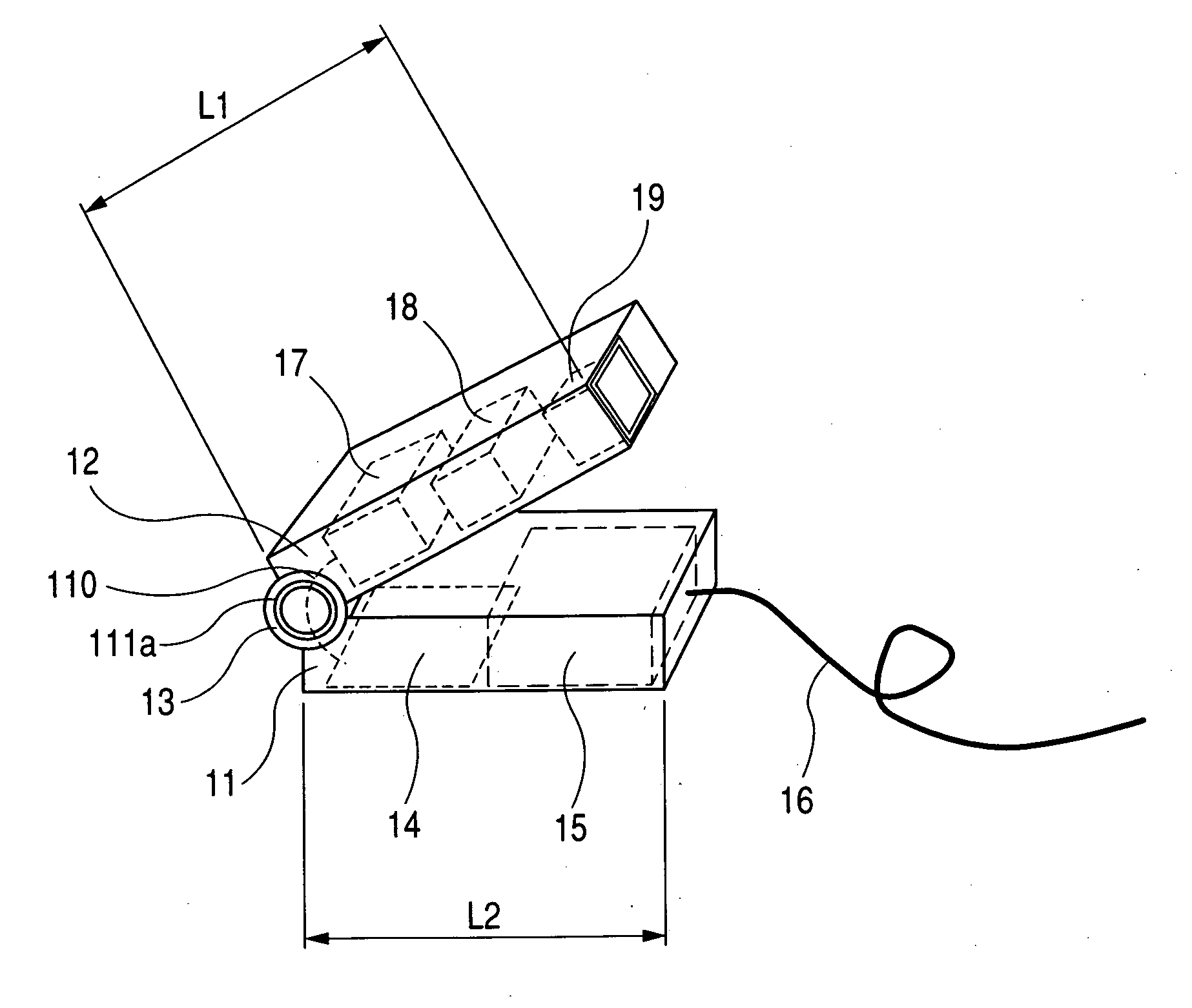
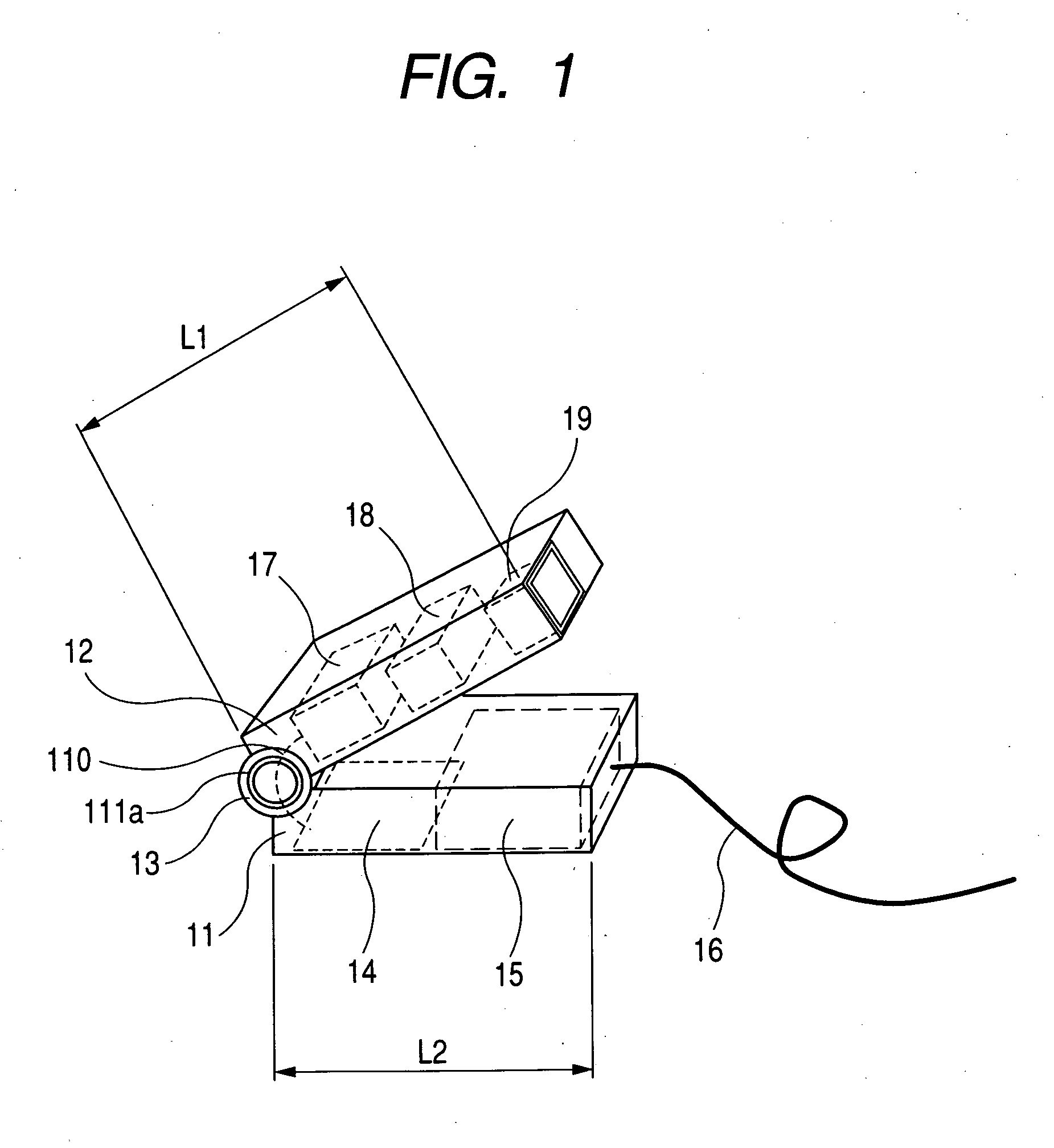
[0053]FIG. 1 is a principal part perspective view showing a video projection apparatus according to a first embodiment of the present invention.
[0054] In the first embodiment, the video projection apparatus includes a first portion 12 (hereinafter referred to as a head portion) that contains a light source means 17, a video display means 18, and a projection optical system 19, a second portion (hereinafter referred to as a main body) 11 that contains a video signal processing circuit (video signal processing means) 14 and a power source means (power supplying means) 15, and a pivot connection portion 13 serving as a connection means for joining the first and second portions 11 and 12 together. The video display means 18 is, for example, a transmission liquid crystal panel, a reflection liquid crystal panel, or an image forming device such as a digital micro-mirror device (DMD), in which a plurality of pixels are two-dimensionally or one-dimensionally arranged. Here, the number of v...
second embodiment
[0065]FIG. 4 is a principal part perspective view showing a video projection apparatus according to a second embodiment of the present invention. In FIG. 4, the same reference numbers are assigned to elements common to those shown in FIG. 1.
[0066] In this embodiment, the connection means 13 connecting the main body 11 with the head portion 12 is rotatable in two directions, a vertical rotational direction 41 and a horizontal rotational direction 42.
[0067] For example, a state in which the main body 11 and the head portion 12 are folded is set to 0 degree. A permissible rotational angle about the vertical rotational direction 41 is set in a range of 0 degree to 90 degrees. A permissible rotational angle about the horizontal rotational direction 42 is set in a range of −180 degrees to 180 degrees. Therefore, in the video projection apparatus, it is possible to project the video to all locations such as the wall surface and the ceiling without the movement of the main body 11.
[0068]...
third embodiment
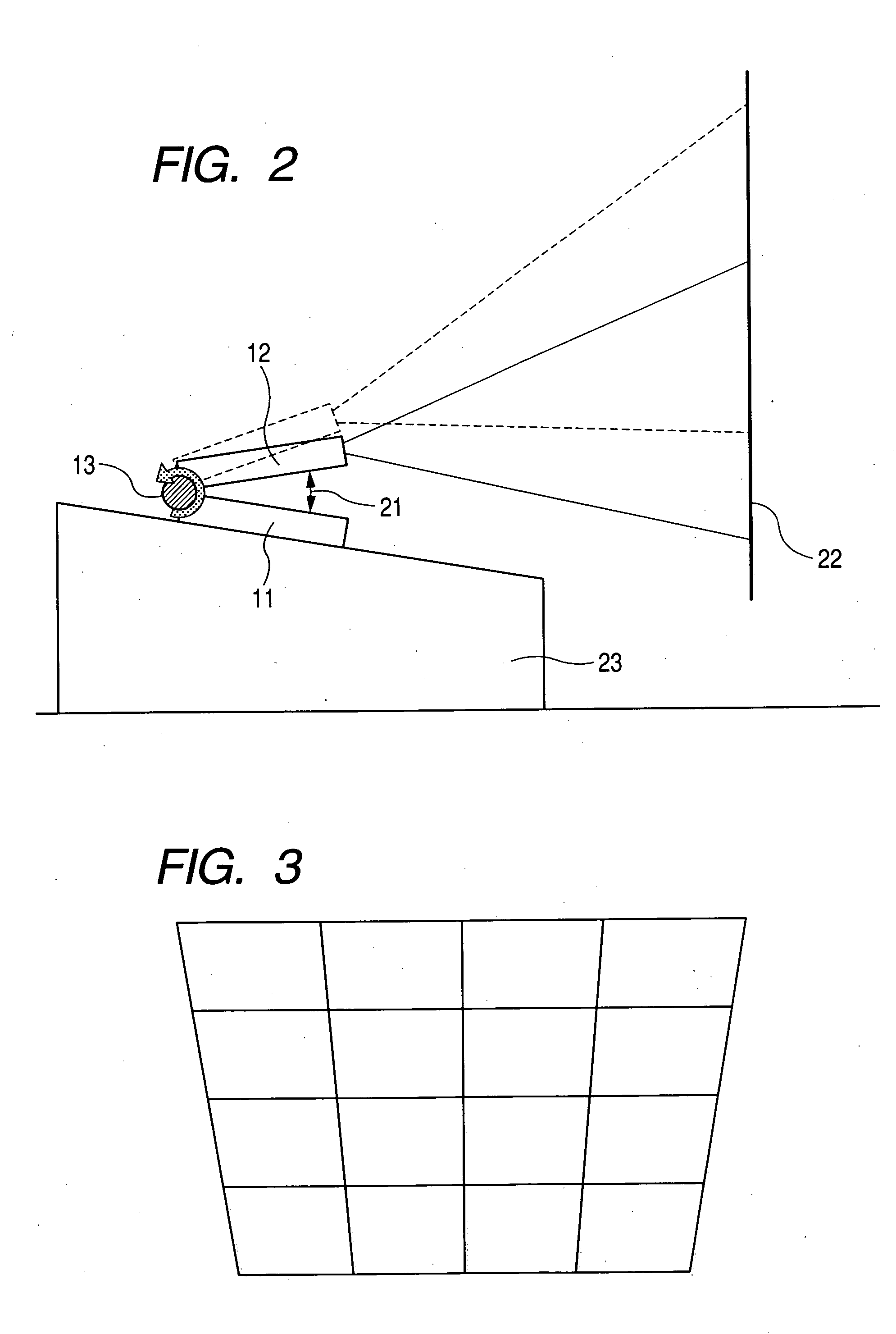
[0081]FIG. 10 is a principal part schematic view showing a video projection apparatus according to a third embodiment of the present invention.
[0082] In this embodiment, a flexible joint 101 which can be driven in an arbitrary direction is used as the connection means for connecting the main body 11 with the head portion 12. The head portion 12 can face in a free direction by the flexible joint 101, so that the video projection direction can be freely set. The main body 11 is idential to that in the second embodiment.
[0083]FIG. 11 is a schematic view showing the flexible joint 101 in this embodiment. As shown in FIG. 11, the flexible joint 101 contains a cable 111 for transmitting a video signal from the video signal processing circuit 14 and a cable 112 for transmitting drive power from the power source means 82. The cables 111 and 112 are surrounded with a flexible tube 113 having flexibility with which it is easy to bend by hand and rigidity with which the head portion 12 is su...
PUM
 Abstract
Description
Claims
Application Information
 - R&D
- Intellectual Property
- Life Sciences
- Materials
- Tech Scout
- Unparalleled Data Quality
- Higher Quality Content
- 60% Fewer Hallucinations
Browse by: Latest US Patents, China's latest patents, Technical Efficacy Thesaurus, Application Domain, Technology Topic, Popular Technical Reports.
© 2025 PatSnap. All rights reserved.Legal|Privacy policy|Modern Slavery Act Transparency Statement|Sitemap|About US| Contact US: help@patsnap.com