Picture color tone controlling method and apparatus

a color tone and control method technology, applied in the field of picture color tone control methods and apparatuses, can solve the problems of high cost of spectrometer, large amount of paper loss after printing process, and inability of spectrometer to follow up measurement objects, etc., to achieve the effect of improving the accuracy of color tone control

Inactive Publication Date: 2006-03-16
MITSUBISHI HEAVY IND LTD
View PDF9 Cites 15 Cited by
  • Summary
  • Abstract
  • Description
  • Claims
  • Application Information

AI Technical Summary

Benefits of technology

[0025] It is an object of the present invention to provide a picture color tone controlling method and apparatus wherein a noticed place (noticed pixel) for control can be set arbitrarily to enhance the accuracy in color tone control.

Problems solved by technology

The spectrometer requires a high cost.
Further, where an object of measurement (in this instance, a printing sheet) moves at a very high speed as in the case of a rotary press for newspapers, the spectrometer cannot follow up the measurement object because of the processing capacity thereof.
Further, in the method described above, since the color tone control is started after an OK sheet is printed, a great amount of paper loss appears after the printing process is started until the OK sheet is printed.
Therefore, where the image line ratio of the picture in a key zone is low, a measurement error of the spectrometer increases and the control is likely to be rendered instable.
Incidentally, according to the technique described above, when it is tried to automatically set a noticed pixel, a pixel (one pixel or a plurality of contiguous pixels in a mass) having a maximum autocorrelation is set as a noticed pixel, while a basic unit for pixels to be printed is a pixel unit of plate making data, according to an IRGB densitometer which is a sensor for measuring the actual color mixture halftone density, it becomes more difficult to secure the resolution as the printing speed increases, and the resolution of the densitometer drops significantly when compared with the resolution of the plate making data.
This deteriorates the density detection sensitivity and hence deteriorates the accuracy in color tone control.

Method used


Image

  • Picture color tone controlling method and apparatus
  • Picture color tone controlling method and apparatus
  • Picture color tone controlling method and apparatus

Examples


first embodiment

A. First Embodiment

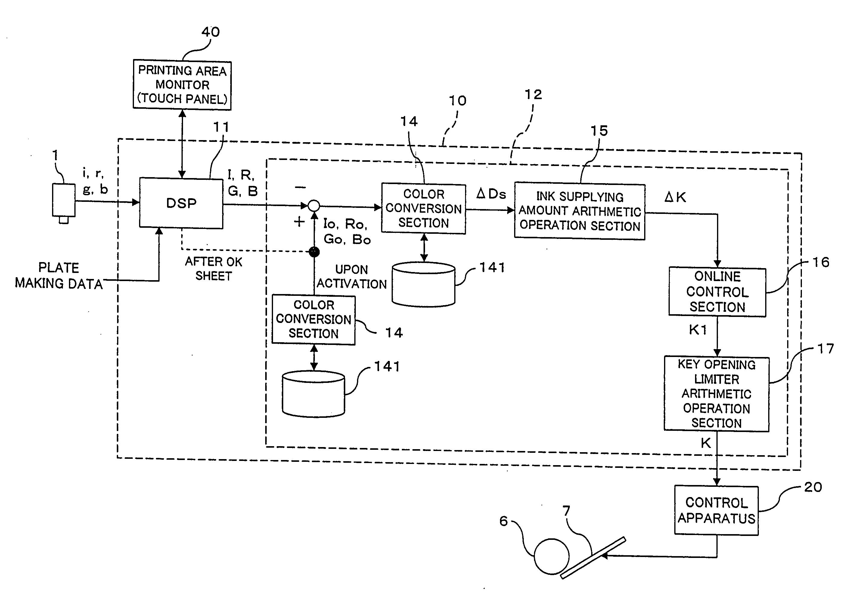
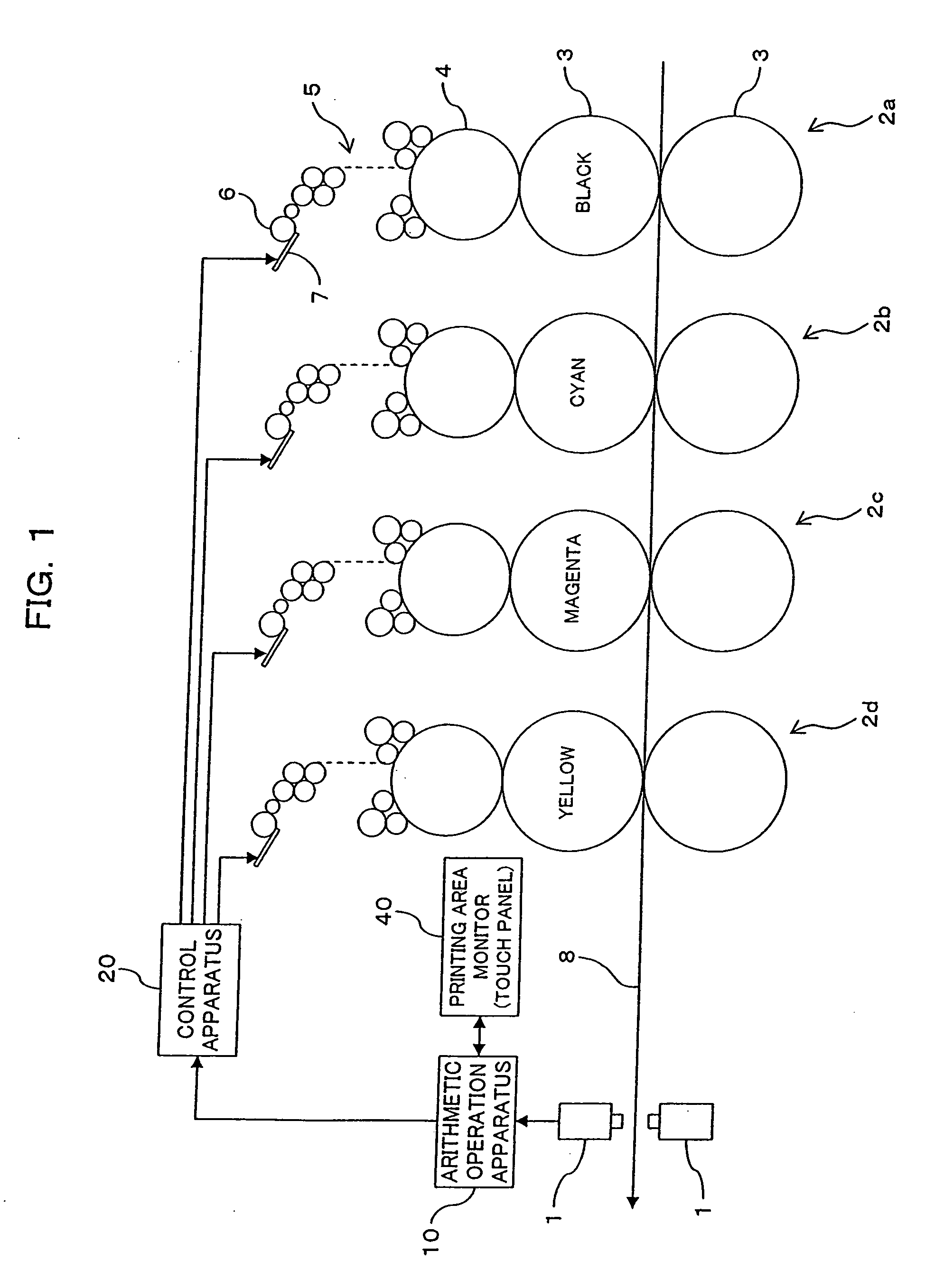
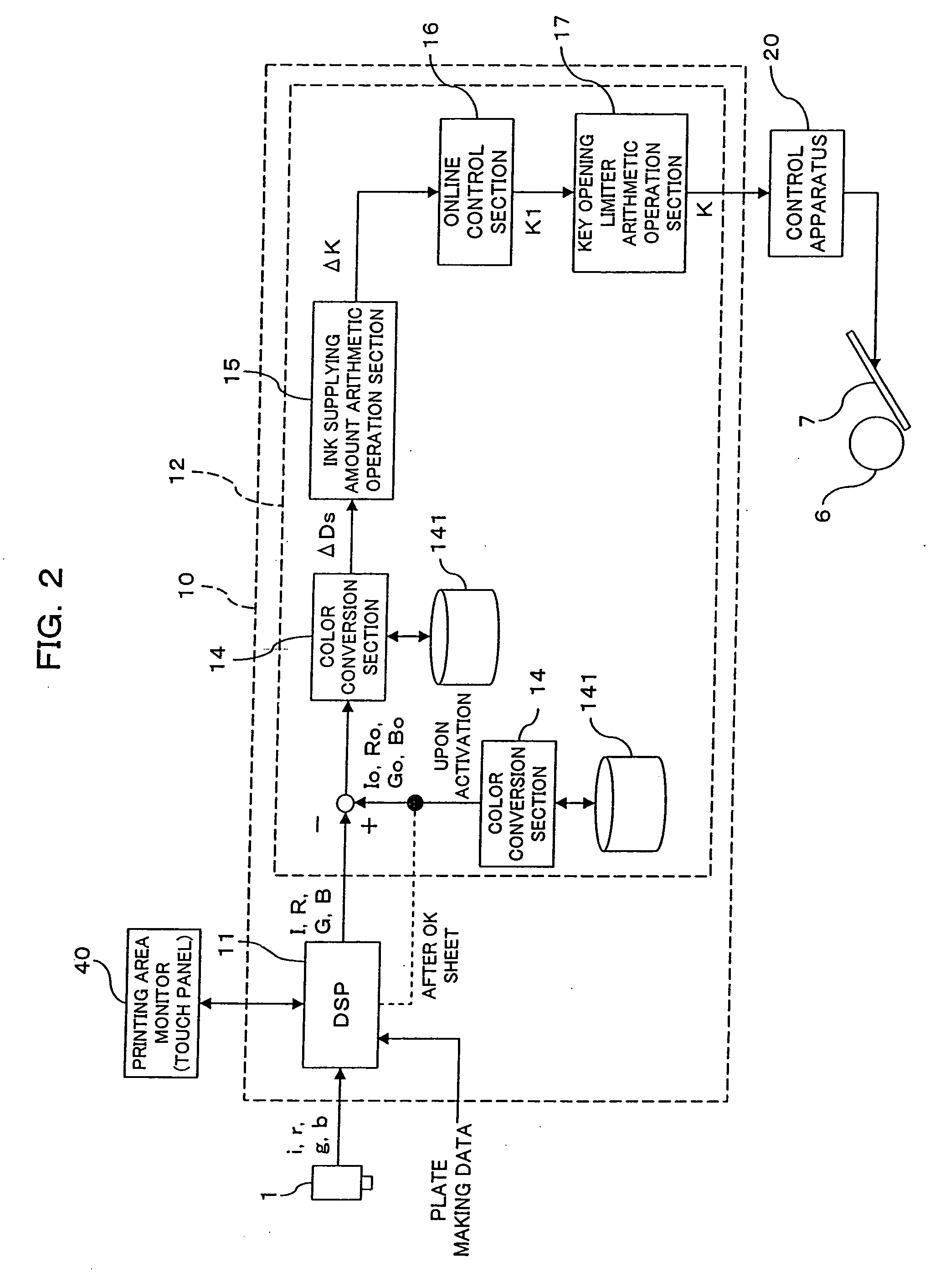
[0074]FIG. 1 shows a general configuration of an offset rotary press for newspapers according to a first embodiment of the present invention. The offset rotary press for newspapers of the present embodiment is a double-sided printing press for multi-color printing and includes printing units 2a, 2b, 2c and 2d disposed for different ink colors [black (k), cyan (c), magenta (m) and yellow (y)] along a transport path of a printing sheet 8. In the present embodiment, each of the printing units 2a, 2b, 2c and 2d includes an ink supplying apparatus of the ink key type which includes a plurality of ink keys 7 and an ink fountain roller 6. In the ink supplying apparatus of the type described, the ink supplying amount can be adjusted by the gap amount (the gap amount is hereinafter referred to as ink key opening) of each of the ink keys 7 from the ink fountain roller 6. The ink keys 7 are juxtaposed in the printing widthwise direction, and the ink supplying amount can be a...

second embodiment

B. Second Embodiment

[0122] A second embodiment of the present invention is described with reference to FIG. 10. Also in the present embodiment, a noticed pixel is set in a similar manner as in the first embodiment.

[0123] It is assumed that, also in the present embodiment, printing data of page information for a newspaper transmitted in the form of bitmap data from the head office of a newspaper company to a printing factory are inputted similarly as in the first embodiment. However, in the present embodiment, as a first difference from the first embodiment, also an ICC profile of an inputting apparatus by which color information of the page has been produced is transmitted in addition to the bitmap data of the page information. At step S321, the bitmap data are converted into low resolution data corresponding to CIP3 data according to the format of the printing press, and at step S322, a noticed point corresponding to each ink color is set for each ink supplying unit width.

[0124] ...

third embodiment

[0130] A third embodiment of the present invention is described with reference to FIG. 11. The present embodiment proposes an auxiliary method for color tone control and can be applied additionally to both of the color control methods of the first and second embodiments. It is to be noted that, in the present third embodiment, a noticed pixel is set in a similar manner as in the first embodiment.

[0131] At step S401, the conversion table recorded in the database 141 is used to convert the target color mixture halftone densities Io, Ro, Co, Bo into color coordinate values (target color coordinate values) (this function is defined as target color coordinate value arithmetic obtainer (arithmetic operation means)). At step S402, the conversion table is used similarly to convert the actual color mixture halftone densities I, R, G, B into color coordinate values (actual color coordinate values) (this function is defined as actual color coordinate value arithmetic obtainer (arithmetic oper...


PUM

PropertyMeasurementUnit
area ratioaaaaaaaaaa
halftone densityaaaaaaaaaa
densityaaaaaaaaaa

Abstract

A picture color tone controlling method and apparatus for a printing press is disclosed by which a noticed pixel for control can be set appropriately and the accuracy in color tone control can be enhanced. For each of ink supplying unit widths, a region which has a high autocorrelation for each of the ink colors is selected in a sensor pixel unit of a densitometer, and a region obtained by removing an edge portion of the pertaining ink color having a width of a predetermined number of pixels from the selected region is set as a noticed pixel for each of the ink colors. Then, a target color mixture halftone density is set for each of the ink supplying unit widths, and an actual color mixture halftone density for each of the ink supplying unit widths of an actually printed sheet is measured using the densitometer. Further, the color mixture halftone density is converted into a halftone dot area ratio and further into a monochromatic halftone density. Then, a solid density deviation is determined, and the ink supplying amount is adjusted for each of the ink supplying unit widths in response to the solid density deviation.

Description

[0001] The application claims the benefit of Japanese Application Serial No. 2004-263912, filed Sep. 10, 2004, which is incorporated herein by reference in its entirety. BACKGROUND OF THE INVENTION [0002] 1) Field of the Invention [0003] This invention relates to a picture color tone controlling method and apparatus for a printing press, and more particularly to a picture color tone controlling method and apparatus for controlling the color tone using an IRGB densitometer. [0004] 2) Description of the Related Art [0005] Various techniques have been proposed as a technique for color tone control of a picture of a printing press. [0006] For example, in techniques disclosed in Japanese Patent Laid-Open No. 2001-18364 (hereinafter referred to as Patent Document 1) and Japanese Patent Laid-Open No. 2001-47005 (hereinafter referred to as Patent Document 2), color tone control is performed in such a procedure as described below. [0007] First, a spectral reflectance of a picture printed ref...

Claims


Application Information

Patent Timeline
Patent Type & Authority Applications(United States)
IPC IPC(8): G03F3/08
CPCB41F33/0045
Inventor OZAKI, IKUOTAKEMOTO, SYUUICHITASAKA, NORIFUMI
Owner MITSUBISHI HEAVY IND LTD
Why Eureka
Try Eureka