Data processing unit and DC backup power supply

a data processing unit and backup power supply technology, applied in the direction of dc source parallel operation, record information storage, resistance welding apparatus, etc., can solve the problems of increased cost, increased heat radiation design of the and increased unit compactness, so as to achieve compact and economic dc backup power supply

Inactive Publication Date: 2006-03-16
HITACHI INFORMATION & TELECOMM ENG LTD
View PDF21 Cites 67 Cited by
  • Summary
  • Abstract
  • Description
  • Claims
  • Application Information

AI Technical Summary

Benefits of technology

[0013] According to a preferred embodiment of the present invention, a compact and economical data processing unit such as disk array unit can be

Problems solved by technology

However, since nickel-metal hydride battery has higher discharge capacity per unit time than conventional lead storage battery, heat radiation design of the DC backup power supply is difficult.
In particul

Method used


Image

  • Data processing unit and DC backup power supply
  • Data processing unit and DC backup power supply
  • Data processing unit and DC backup power supply

Examples


first embodiment

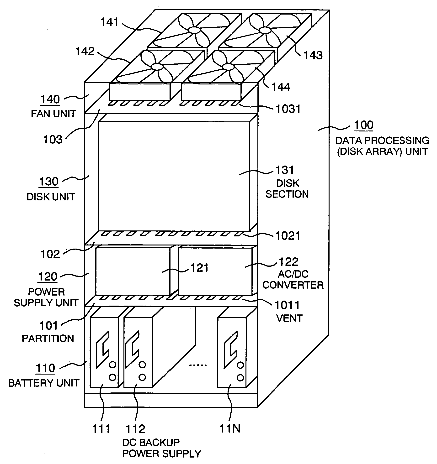
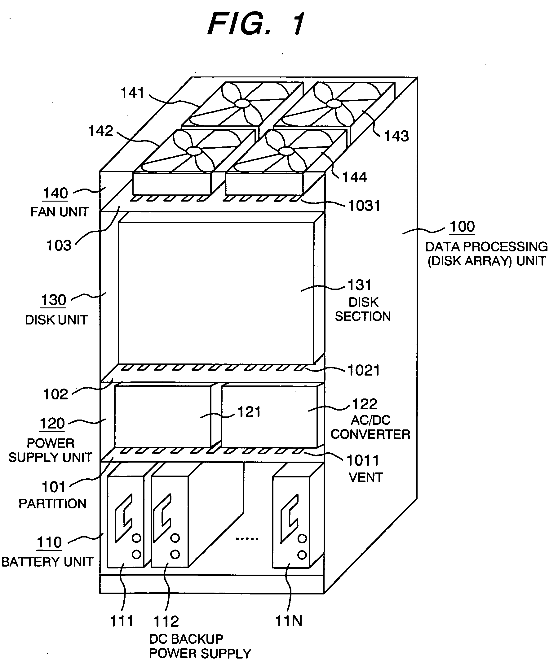
[0031]FIG. 1 is an oblique view of the brief construction of a disk array unit as an example of the data processing unit equipped with a DC backup power supply (hereinafter called the backup power supply) according to the present invention. The disk array unit 100 having a rack structure is separated vertically into multiple-storied storage spaces by multiple partitions 101, 102, 103. In this embodiment, there are four stories of storage spaces, each for battery unit 110, power supply unit 120, disk unit 130, and fan unit 140 from the bottom to the top in this order. In the battery unit 110 on the bottom, N sets of DC backup power supplies 111, 112, up to 11N are mounted. In the power supply unit in the storage space right above it, two AC / DC converters 121, 122 are mounted. In the disk unit 130 right above it, a disk section 131 comprising multiple hard disk drives (HDDs) and controllers is mounted. In the fan unit 140 at the top storage space, four fans 141 to 144 are mounted.

[003...

second embodiment

[0049]FIG. 8 is an oblique view of the brief construction of part of a disk array unit as the data processing unit equipped with the backup power supply according to the present invention. The same symbol as in FIG. 1 represents the same part / component and so no duplicate description is given. The figure shows a brief construction of the battery unit 110 and power supply unit 820 of the disk array unit 100. The cooling system of the unit is based on bottom suction and top exhaust, where a secondary fan 822 is mounted as well in the AC / DC converter 821 and the power semiconductor devices inside the converter 821 are cooled by the ventilation from the bottom to the top by this fan 822. A sufficient size of an opening 8011 is provided in the partition between the battery unit 110 and power supply unit 820 so that the backup power supplies 111, 112, etc. can be cooled by the fan 822. Rows of storage rails 802 are provide on the bottom of the battery unit 110 so that multiple backup powe...


PUM

PropertyMeasurementUnit
Forceaaaaaaaaaa
Electrical resistivityaaaaaaaaaa
Thermal conductivityaaaaaaaaaa

Abstract

A backup power supply is so constructed that it is provided with multiple DC backup power supplies 111 to 11N, each containing nickel-metal hydride battery, stored upright on the bottom of the disk array unit 100; cooled by cooling air through the vents 1011 for ventilation from the bottom to the top; and connected with the output of the AC/DC converters 121, 122 with the backboard 151. Very compact disk array unit with an uninterruptible power supplying function can be realized.

Description

CLAIM OF PRIORITY [0001] The present application claims priority from Japanese application serial no. 2004-263555, filed on Sep. 10, 2004, the content of which is hereby incorporated by reference into this application. FIELD OF THE INVENTION [0002] The present invention relates to a data processing unit such as disk array unit equipped with DC backup power supply and to a DC backup power supply that backs up the power supply to loads by means of various types of secondary battery such as nickel-metal hydride battery or lithium battery. BACKGROUND OF THE INVENTION [0003] A data processing unit such as disk array unit used as an external memory of a computer is equipped with a UPS (uninterruptible power supply) against power failure or auxiliary energy source such as storage battery that backs up important loads such as cash memory. [0004] Lately, a DC type UPS that supplies DC power to loads in case of power failure such as momentary stoppage or interruption of commercial power, that...

Claims


Application Information

Patent Timeline
IPC IPC(8): H05K5/00G06F1/20G06F1/26G11B33/12G11B33/14H01M2/10H01M10/44H01M10/60H01M10/613H01M10/627H01M10/643H01M10/647H01M10/651H01M10/653H01M10/6556H01M10/6563H01M10/6566
CPCG06F1/30G11B33/142G11B33/126G11B33/12G11B33/14
Inventor TAKAHASHI, FUMIKAZUKANOUDA, AKIHIKOHAMAOGI, MASAHIROTAKAHASHI, YOSHIHIDE
Owner HITACHI INFORMATION & TELECOMM ENG LTD
Why Eureka
Try Eureka