Method for identifying an image of a well in an image of a well-bearing component

a well-bearing component and image technology, applied in the field of cell biology, can solve the problems of difficult high-throughput imaging (for example morphological studies), inconvenient multi-well plate study of individual cells or even small groups of cells, and inability to find specific individual cells for observation, etc., to achieve quick, accurate and robust delineation

Inactive Publication Date: 2006-03-16
SENG ENTERPRISES
View PDF89 Cites 38 Cited by
  • Summary
  • Abstract
  • Description
  • Claims
  • Application Information

AI Technical Summary

Benefits of technology

[0035] The present invention successfully addresses at least some of the shortcomings of the prior art by providing a method for identifying the image of a well in an image of a well-bearing component as well as of a device for implementing the method of the present invention. Embodiments of the present invention also provide for the quick, accurate and robust delineation of the borders of the images of the well.,
[0036] The present invention uses the optical properties of well-bottoms to identify the images of respective wells of a well-bearing component. Some or all embodiments of the present invention have advantages including applicability to occupied and unoccupied wells, delineation of images of signal-less occupied wells, allow the use of observation components such as CCD devices as multi-signal detectors, allows delineation of a well image irrespective of the well-bearing component orientation and allows the observation component to be located above or below the well-bearing component.
[0067] In an embodiment of the present invention, at least one image of the well-bearing component is stored, preferably as digital data. In an embodiment of the present invention, prior to storing, the amount of digital data stored is reduced by removing and / or discarding data not corresponding to images of the wells.

Problems solved by technology

Although exceptionally useful for the study of large groups of cells, multiwell plates are not suitable for the study of individual cells or even small groups of cells due to the large, relative to the cellular scale, size of the wells.
When cells float about in a well, specific individual cells are not easily found for observation.
Such variability in location makes high-throughput imaging (for example for morphological studies) challenging as acquiring an individual cell and focusing thereon is extremely difficult.
Such variability in location also makes high-throughput signal processing (for example, detection of light emitted by a single cell through fluorescent processes) challenging as light must be gathered from the entire area of the well, decreasing the signal to noise ratio.
Further, a cell held in a well of a multiwell plate well can be physically or chemically manipulated (for example, isolation or movement of a single selected cell or single type of cell, changing media or introducing active entities) only with difficulty.
An additional disadvantage of multiwell plates is during the study of cells undergoing apoptosis.
However, once a cell begins the apoptosis process, the adhesion of the cell to the bottom of the well is no longer sufficient: the cell detaches from the bottom and is carried away by incidental fluid currents in the well.
An additional disadvantage of multiwell plates is in the study of non-adhering cells.
Considering that non-adhering cells are crucial for research in drug discovery, stem cell therapy, cancer and immunological diseases detection, diagnosis, therapy this is a major disadvantage.
The fact that the cells are not free-floating but are bound to the plate through some interaction necessarily compromises the results of experiments performed.
Further, the suction required to hold cells in picowells of a carrier of U.S. Pat. No. 4,729,949 deforms held cells and makes a significant portion of the cell membranes unavailable for contact, both factors that potentially compromise experimental results.
Study of cells with non-fluorescence based methods generally gives poor results due to reflections of light from the carrier.
The fact that emitted light travels through an optical fiber leads to loss of time-dependent and phase information.
One of the challenges of well-bearing devices known in the art for the study of single living cells, especially picowell-bearing devices, is of information acquisition.
Manual image analysis is time-consuming, incompatible with high-throughput studies and is not generally applicable.
A disadvantage of using automatic image analysis is that there is no easy way to sift through the massive amount of information acquired to identify important events from amongst all the images acquired.
One of the greatest challenges in both automatic image analysis and automatic signal analysis is the delineation of the borders of a single cell.
In both such cases, analysis of an image or of a signal gives completely wrong results.
Further, due to the fact that the material from which wells are made is not invisible, distortions, reflections, diffractions and the image of the picowell walls often make delineation of cells difficult.
For example, differentiating cell 42 from cell 44 in FIG. 3 is a difficult task.
It is important to note that even the imperfect methods known in the art are time consuming, expensive in terms of calculation resources, not robust and in general unsuited for high-throughput applications.
The problem of delineating the borders of a cell for automatic signal analysis is even greater.
In such applications, it is not practical to have a time consuming cell-identification or picowell-identification step.
In addition, if the borders of the cell or picowells are not clearly delineated, the quality of the data is seriously compromised.
An additional problem arises when what is to be detected is not light emitted by a cell itself but rather light emitted by chromatogenic or fluorogenic entitities in the medium in the immediate area of the cell, for example the medium held together with the cell in the same picowell.
As stated above, amongst other problems associated with the device of PCT patent application U.S.99 / 04473, the fact that the emitted light travels through an optical fiber leads to loss of time dependent and phase information.
Further, the device of PCT patent application U.S.99 / 04473 is not suitable for acquiring high-resolution images.
Such a method requires a highly expensive observation system, including a dedicated, accurately crafted and expensive microlens array.

Method used


Image

  • Method for identifying an image of a well in an image of a well-bearing component
  • Method for identifying an image of a well in an image of a well-bearing component
  • Method for identifying an image of a well in an image of a well-bearing component

Examples


Embodiment Construction

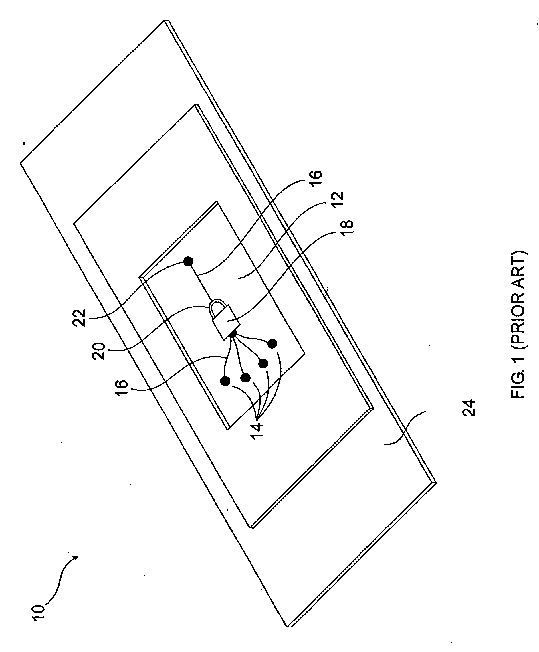
[0089] The present invention is of a method for identifying an image of a well in an image of a well-bearing component, for example in the field of biology during optical study of cells. The present invention is also of a device useful in implementing the method of the present invention.

[0090] The principles, uses and implementations of the teachings of the present invention may be better understood with reference to the accompanying description and figures. Upon perusal of the description and figures present herein, one skilled in the art is able to implement the teachings of the present invention without undue effort or experimentation. In the figures, like reference numerals refer to like parts throughout.

[0091] Before explaining at least one embodiment of the invention in detail, it is to be understood that the invention is not limited in its application to the details set forth herein. The invention can be implemented with other embodiments and can be practiced or carried out...


PUM

PropertyMeasurementUnit
diameteraaaaaaaaaa
volumeaaaaaaaaaa
sizeaaaaaaaaaa

Abstract

A method for identifying images of wells in an image of a well-bearing object such as multiwell plates or picowell carriers is provided. An observation component, such as a camera, is used to approach focus of a focal point of a well-bottom. An image of the focal point is acquired. The image of the well-bottom focal point is then used as a reference point or used to define a reference point from which to identify the image of the well in the image of the well-bearing component and from which to delineate the borders of the well.

Description

FIELD AND BACKGROUND OF THE INVENTION [0001] The present invention relates to the field of cellular biology and more particularly, to an improved device and method for the study of cells. Specifically, the present invention is a method and a device for identification of the image of individual wells in an image of a well-bearing component so as to allow efficient image analysis and signal detection of cells held in the wells. [0002] Combinatorial methods in chemistry, cellular biology and biochemistry are essential for the near simultaneous preparation of multitudes of active entities such as molecules. Once such a multitude of molecules is prepared, it is necessary to study the effect of each one of the active entities on a living organism. [0003] The study of the effects of stimuli such as exposure to active entities on living organisms is preferably initially performed on living cells. Since cell-functions include many interrelated pathways, cycles and chemical reactions, the stu...

Claims


Application Information

Patent Timeline
Patent Type & Authority Applications(United States)
IPC IPC(8): C12Q1/00
CPCG01N21/0303G06T7/0012G06T2207/30072G06T2207/10064G06T2207/30024G06T7/0081Y10S128/922G06T7/11
Inventor DEUTSCH, MORDECHAIKAUFMAN, MENACHEM
Owner SENG ENTERPRISES
Why Eureka
Try Eureka