Electric equipment

Inactive Publication Date: 2006-03-16
NIDEC CORP
View PDF20 Cites 3 Cited by
  • Summary
  • Abstract
  • Description
  • Claims
  • Application Information

AI Technical Summary

Benefits of technology

[0012] With the electronic equipment according to the invention, it is possible to prevent the thin circuit board from being inserted into the gap by the effect of the guide formed on the main circuit board. As a result, the thin circuit board can be favorably connected to the inserting port of the connector.
[0013] Furthermore, with the electronic equipment accordin

Problems solved by technology

In this case, the worker must do the inserting work of the FPC 300 again, thereby raising a problem of degradation of productivity by the worker.
As a result, the FPC 300 becomes a defective product, thereby raising a problem of an impossibility of reuse of the FPC 300.
To make matters worse, the shape of the connector

Method used


Image

  • Electric equipment
  • Electric equipment
  • Electric equipment

Examples


first preferred embodiment

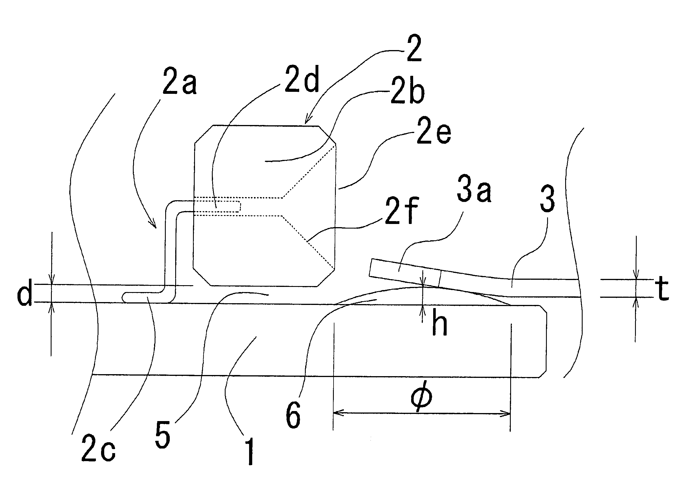
[0019]FIG. 1 is a view schematically showing a first preferred embodiment according to the invention.

[0020] Referring to FIG. 1, a connector 2 is fixed onto a side of a mounting surface (i.e., on an upper side in FIG. 1) of a main circuit board 1 formed by molding paper phenol or the like into a flat plate. The connector 2 is constituted of a terminal 2a and an outside connected portion 2b, which contains a part of the terminal 2a and is molded of an insulating casing made of a resin or the like. The terminal 2a further includes a main circuit board connecting portion 2c, which is not contained inside of the casing and is electrically connected to the main circuit board 1 by soldering, and a thin circuit board connecting portion 2d, which is contained inside of the casing and performs electric connection in contact with an FPC 3 serving as a thin circuit board, described later. At the outside connected portion 2b, an opening is formed as an inserting port 2e with respect to an outs...

second preferred embodiment

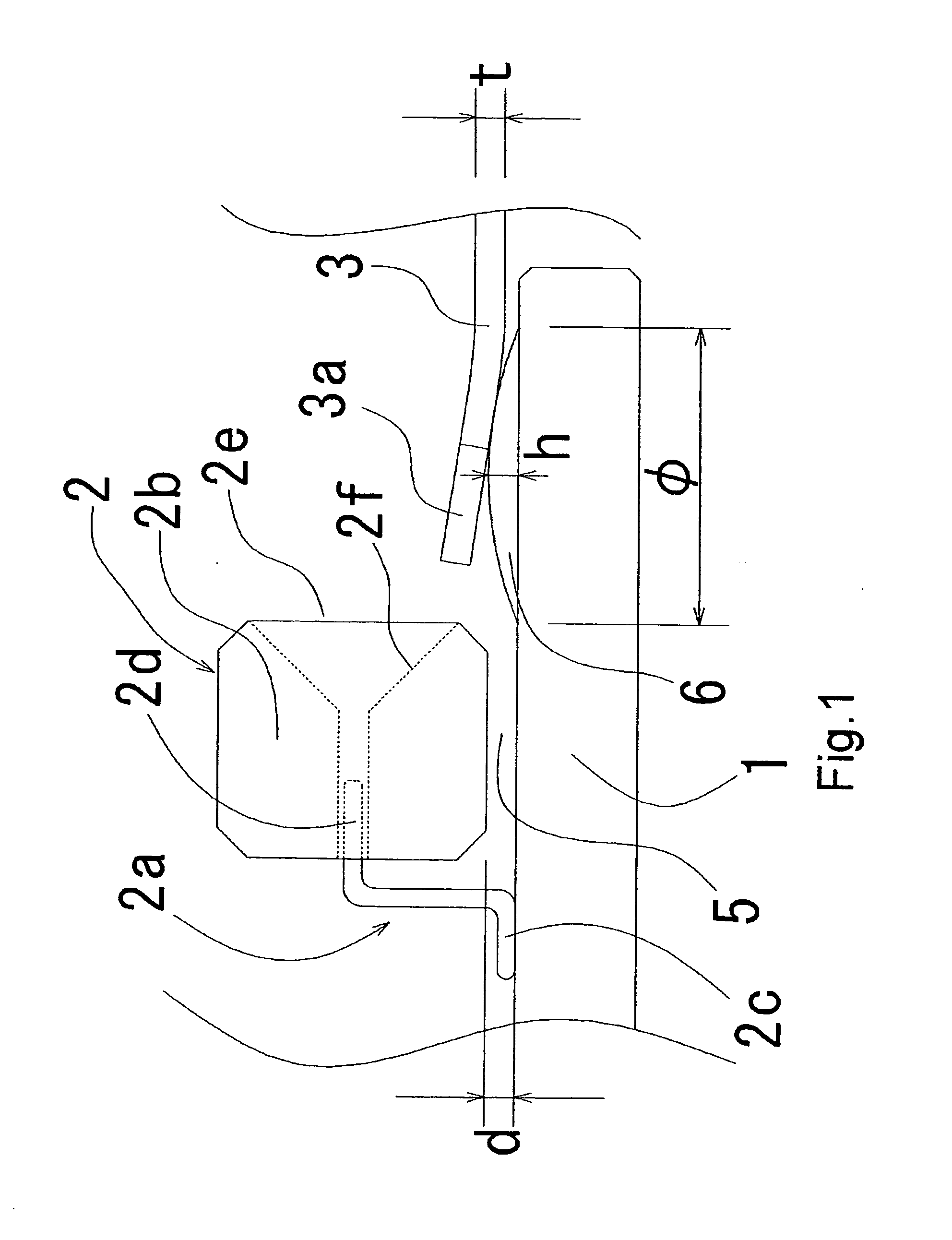
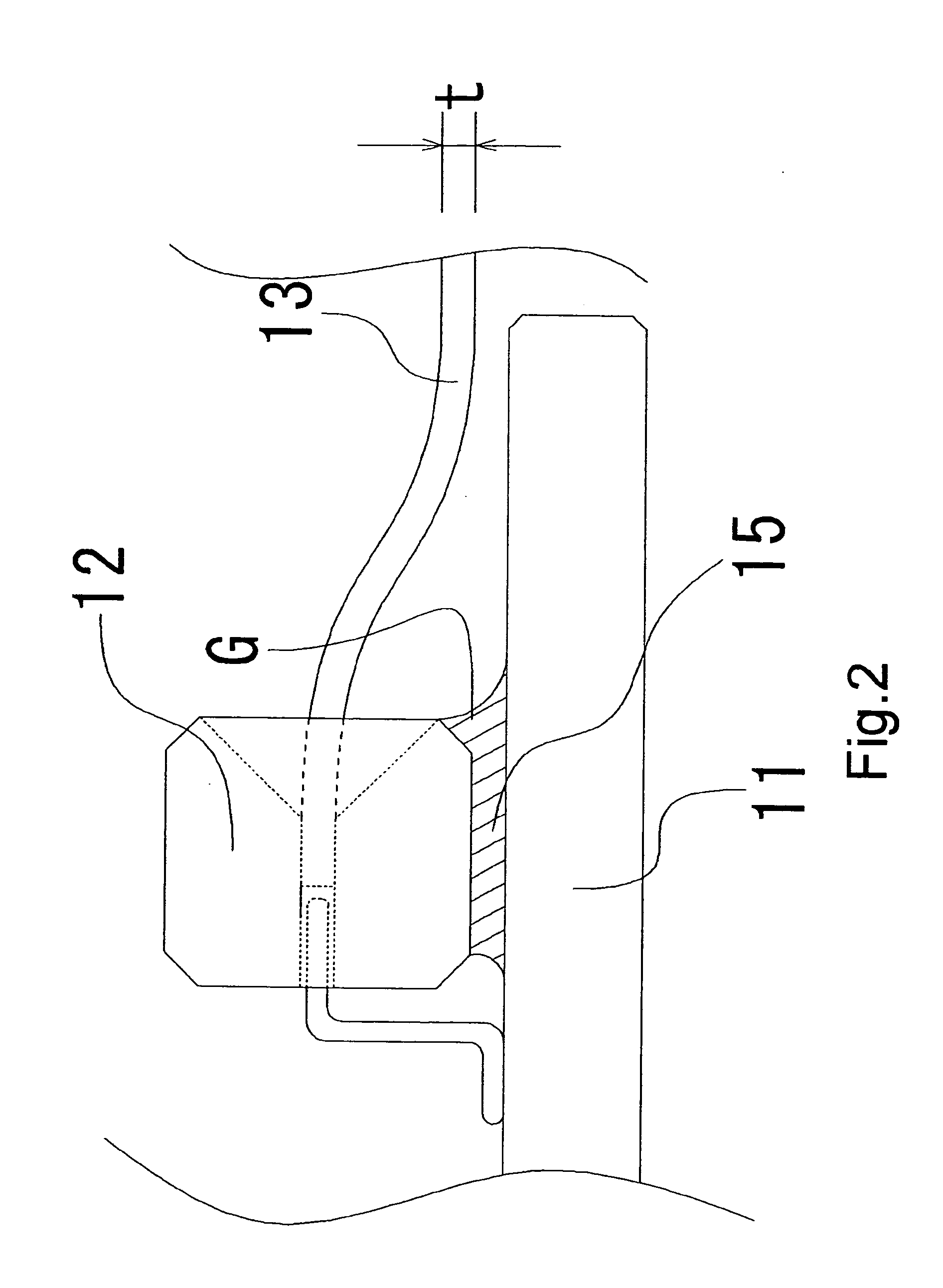
[0025]FIG. 2 is a view schematically showing a second preferred embodiment according to the invention.

[0026] Referring to FIG. 2, a connector 12 is adhesively fixed onto a main circuit board 11, and a thin circuit board 13 is inserted into the connector 12. The thin circuit board 13 in the present preferred embodiment is the same as the thin circuit board 3 in the first preferred embodiment, and therefore, it will be hereinafter referred to as “an FPC 13”.

[0027] In the present preferred embodiment, a gap 15 is formed between the connector 12 and the main circuit board 11, and a right portion, that is, a portion of the gap 15 suspended from an inserting port 12d of the connector 12 is filled with an adhesive agent G. As a result, the FPC 13 can be prevented from intruding into the gap 15 in the present preferred embodiment.

[0028] Here, in the case where the adhesive agent is used, it is necessary to sufficiently examine the materials of the main circuit board 11 and the connector ...

third preferred embodiment

[0030]FIG. 3 is a view schematically showing a third preferred embodiment according to the invention. FIG. 3 shows a recording disk drive device.

[0031] Examples of typical electronic equipment include a recording disk drive device. A recording disk drive device comprises a main circuit board 21, an electric motor 7 for rotating a recording disk, and a head unit, not shown, including a recording head for recording information on the recording disk and a reading head for reading the information, neither shown, and a circuit for transferring the information to the recording or reading head or converting the information.

[0032] The recording disk drive device includes various connecting terminals such as a power source terminal for supplying electric power from an outside power source, an information terminal for transmitting the information between the recording disk drive device and the outside, and another information terminal for transmitting the information between the head unit a...


PUM


Abstract

In order to prevent any erroneous insertion of a thin circuit board 3 into a gap 5 formed between a main circuit board 1 and a connector 2 when the thin circuit board 3 is inserted into an inserting port 2e formed at the connector 2 fixed at a mounting surface of the main circuit board 1 by electric connection, a guide 6 is formed by applying solder onto the mounting surface of the main circuit board 1 and in the vicinity of the inserting port 2e. The guide 6 can prevent any insertion of the thin circuit board 3 into the gap 5.

Description

FIELD OF THE INVENTION [0001] The invention relates to electric equipment, in which electric connection is achieved by inserting a thin circuit board into a connector fixed onto and electrically connected to a main circuit board. BACKGROUND OF THE INVENTION [0002] In electric equipment such as audio equipment, video equipment, a computer and peripheral equipment thereof, functional equipment such as a motor, an actuator or an input / output device is connected to a main circuit board, on which a circuit having a function as a control circuit is mounted. There has been conventionally known a structure for connecting a thin circuit board having flexibility to a connector as a structure for connecting the functional equipment connected onto the main circuit board to a power source. Here, the connector is formed into a shape of a casing, which contains therein a plurality of terminals electrically connected and fixed to the main circuit board by soldering and whose one surface has an inse...

Claims


Application Information

Patent Timeline
IPC IPC(8): H01R12/00
CPCH05K1/117H05K1/14H05K2201/0305H05K2201/09909H01R12/712H05K2201/10446H05K2201/2027H01R12/79H01R12/7005H05K2201/10189
Inventor INUI, AKIRA
Owner NIDEC CORP
Why Eureka
Try Eureka