Highly active slurry catalyst composition

Inactive Publication Date: 2006-03-16
CHEVROU USA INC
View PDF4 Cites 56 Cited by
  • Summary
  • Abstract
  • Description
  • Claims
  • Application Information

AI Technical Summary

Benefits of technology

[0015] This new highly active slurry catalyst composition may be stored in an active and concentrated state. The catalyst composition can be directly introduced into any of the known heavy oil or residuum u

Problems solved by technology

These patents do not demonstrate the criticality of the oil viscosity in the formation of a highly active cataly

Method used


Image

  • Highly active slurry catalyst composition

Examples


example 1

For Catalyst Preparation (with Light Oil)

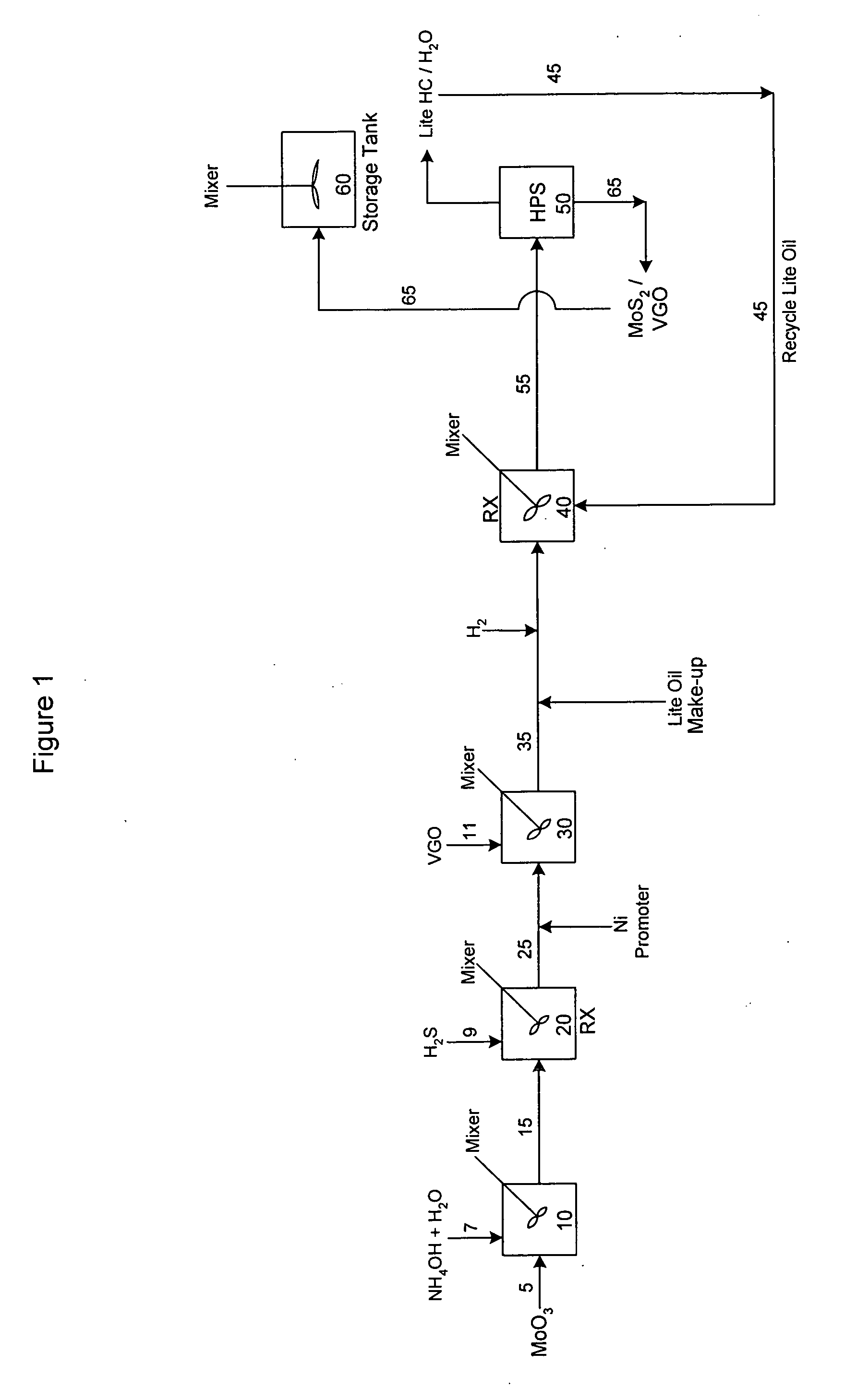
[0026] 540 gram MoO3 is mixed with 79 grams of NH3 and 2381 grams of H2O to form a solution of total 3000 grams. The solution is then reacted with 10.71 SCF of H2S by passing a gas mixture of 20% H2S in H2 into the solution under strong mixing. The reactor temperature is 150° F. and the total pressure is 400 psig, and the reaction time is 4 hours. After reaction, 460 grams NiSO4 solution which contains 36 grams of Ni is added to the above obtained slurry. The obtained slurry mixture is then mixed with 3500 grams of vacuum gas oil at 100° F. The viscosity of the VGO is 5 cSt @ 212° F. The resulting mixture is then pumped into a continuously flow stirred tanked reactor (perfectly mixed flow reactor) and mixed with heptane and H2, the ratio of heptane / VGO is 9:1 and H2 gas rate is 5000 SCF / B. The reactor pressure is 2500 psig and reactor temperature is 400° F., the total reaction time is 1 hour. The reaction products go to a hot high pressure s...


PUM

PropertyMeasurementUnit
Temperatureaaaaaaaaaa

Abstract

The instant invention is directed to the preparation of a catalyst composition suitable for the hydroconversion of heavy oils. The catalyst composition is prepared by a series of steps, involving mixing a Group VIB metal oxide and aqueous ammonia to form an aqueous mixture, and sulfiding the mixture to form a slurry. The slurry is then promoted with a Group VIII metal. Subsequent steps involve mixing the slurry with a hydrocarbon oil and combining the resulting mixture with hydrogen gas and a second hydrocarbon oil having a lower viscosity than the first oil. An active catalyst composition is thereby formed.

Description

FIELD OF THE INVENTION [0001] The present invention relates to the preparation of slurry catalyst compositions useful in the processing of heavy oils. These oils are characterized by low hydrogen to carbon ratios and high carbon residues, asphaltenes, nitrogen, sulfur and metal contents. BACKGROUND OF THE INVENTION [0002] Slurry catalyst compositions and means for their preparation are known in the refining arts. Some examples are discussed below. [0003] U.S. Pat. No. 4,710,486 discloses a process for the preparation of a dispersed Group VIB metal sulfide hydrocarbon oil hydroprocessing catalyst. Process steps include reacting aqueous ammonia and a Group VIB metal compound, such as molybdenum oxide or tungsten oxide, to form a water soluble oxygen-containing compound such as ammonium molybdate or tungstate. [0004] U.S. Pat. No. 4,970,190 discloses a process for the preparation of a dispersed Group VIB metal sulfide catalyst for use in hydrocarbon oil hydroprocessing. This catalyst i...

Claims


Application Information

Patent Timeline
IPC IPC(8): B01J35/12B01J31/00B01J27/02
CPCB01J27/0515C10G2300/1074B01J35/12B01J37/20C10G47/26C10G49/04C10G49/12C10G65/04C10G67/0454C10G2300/1033C10G2300/207C10G2300/703C10G2300/1003C10G2300/1022B01J27/053B01J27/051B01J31/00B01J27/02
Inventor CHEN, KAIDONGLEUNG, PAK C.REYNOLDS, BRUCE E.
Owner CHEVROU USA INC
Why Eureka
Try Eureka