
Integrated anesthesia monitoring and ultrasound display

an anesthesia monitoring and ultrasound display technology, applied in the field of cardiac care systems, can solve the problems of tripping over or damaging cables or other instruments, limiting the positioning of both the ultrasound unit and the anesthesia monitoring unit, and the available space in most operating rooms, so as to reduce clutter

Inactive Publication Date: 2006-03-16
GENERAL ELECTRIC CO
View PDF12 Cites 36 Cited by
  • Summary
  • Abstract
  • Description
  • Claims
  • Application Information

AI Technical Summary

Benefits of technology

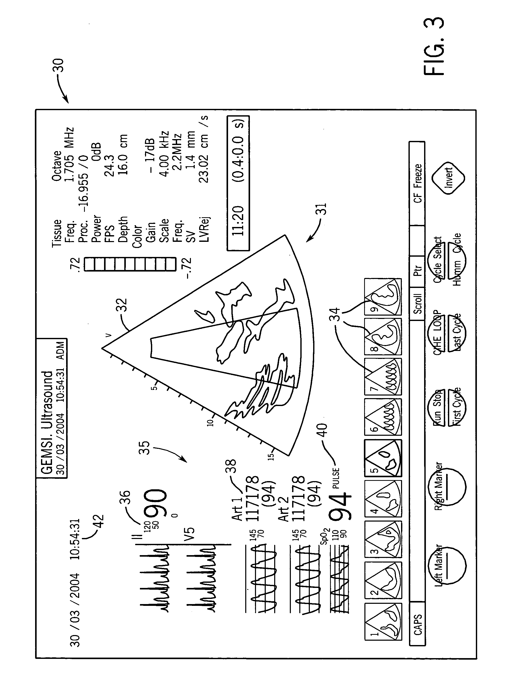
[0009] The present invention is a system and method that integrates the functionality of an ultrasound scanning system and a patient monitoring system, such as an anesthesia monitoring system. Preferably, the integration will occur at three different levels. First, the ultrasound system and the anesthesia monitoring system may be mechanically coupled such that both displays are on the same plane of view, with the ultrasound system receiving the hemodynamic monitoring information or vice versa. This mechanical coupling will allow the clinician to reduce the clutter within an operating room theater.
[0011] Third, the integrated system allows the monitored data from both the ultrasound and anesthesia monitoring systems to be saved digitally and with time synchronization such that the hemodynamic measurements can accurately be correlated with the heart function as depicted by the synchronized ultrasound image. The synchronization of the hemodynamic measurements and the ultrasound images allows a clinician to review the monitored information at a later time or simultaneously to the data / image acquisition from a remote location and obtain the required information from the combined data.
[0014] After both the hemodynamic measurements and the ultrasound images are stored, a clinician can review the ultrasound images and the hemodynamic measurements at a later time or from a remote location. Preferably, the ultrasound images and the hemodynamic measurements will be displayed on an integrated display device. However, the use of multiple displays to show the time synchronized information from the ultrasound monitoring system and the anesthesia monitoring system allows the clinical to obtain a complete understanding of the patient's condition at a time either before or after the ultrasound images are recorded.

Problems solved by technology

Although the position of the two monitoring units can be adjusted within the operating room, the available space in most operating rooms severely limits the positioning of both the ultrasound unit and the anesthesia monitoring unit.
The use of separate anesthesia patient monitoring and ultrasound monitoring systems presents several different challenges to a clinician.
As described, since space in the operating room is at a premium, the size of a traditional ultrasound system occupies considerable real estate near the surgical table.
Further, since a traditional ultrasound system can weigh up to 400 lbs., moving the ultrasound system from one operating room suite to another during surgery can result in tripping over or damaging cables or other instruments.
One of the significant challenges of utilizing separate anesthesia patient monitoring systems and ultrasound systems is the time-based synchronization of the two displays when reviewing stored information.
However, the stored images from the ultrasound unit and the hemodynamic measurements from the anesthesia patient monitoring system are not integrated with each other, such that the time-based stored information is not correlated or synchronized to the other unit.

Method used


Image

  • Integrated anesthesia monitoring and ultrasound display
  • Integrated anesthesia monitoring and ultrasound display
  • Integrated anesthesia monitoring and ultrasound display

Examples


Embodiment Construction

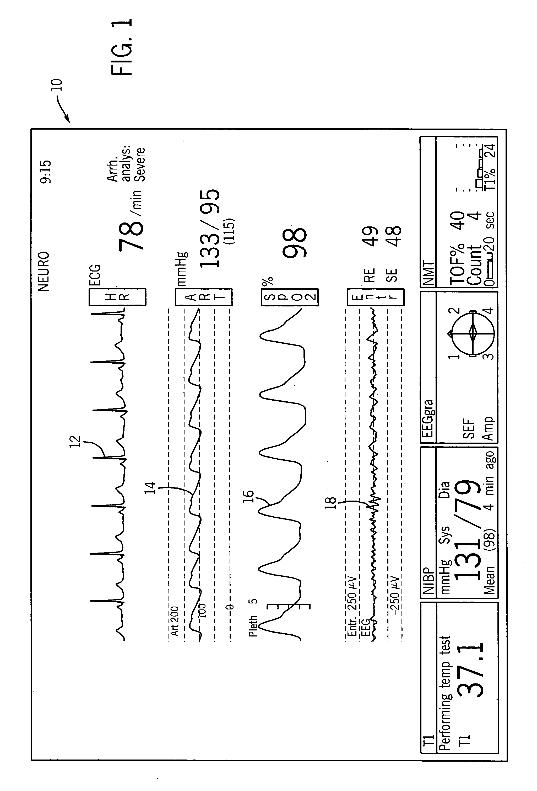
[0028] Referring first to FIG. 1, thereshown is a conventional display 10 that is typically found in a hemodynamic patient monitoring system. The hemodynamic patient monitoring system has a variety of different uses and is widely used in the operating room during procedures requiring the use of anesthesia. As illustrated in FIG. 1, the standard anesthesia display 10 graphically depicts a series of hemodynamic measurements including at least one ECG trace 12, an invasive blood pressure trace 14, an oxygen saturation trace 16 and an entropy trace 18. Each of the traces 12-16 is made and presented on the display 10 in real time and presents the user with the required information to monitor the patient during the anesthesia procedure. The individual traces 12-18 are conventional hemodynamic measurements and are widely utilized in the operating room environment.

[0029] Although the following description will make particular reference to a hemodynamic anesthesia monitoring system, it shou...


PUM


Abstract

An apparatus and method for synchronizing the hemodynamic measurements from a patient monitoring system and the ultrasound images from an ultrasound monitoring system. The synchronized images and measurements can be combined and displayed on a single display that includes both the ultrasound images and the hemodynamic patient measurements. The combined display receives synchronized information from both the ultrasound monitoring system and the hemodynamic patient monitoring system and displays the combined information on a single monitor. In addition to displaying the synchronized combined information, the system stores the synchronized information for later playback. The playback of the stored images and measurements is synchronized such that the clinician can be presented with the combined information in a usable manner.

Description

CROSS REFERENCE TO RELATED APPLICATION [0001] The present application is based on and claims priority to U.S. Provisional Patent Application Ser. No. 60 / 610,473, filed Sep. 16, 2004.BACKGROUND OF THE INVENTION [0002] The present invention relates to a cardiovascular care system that synchronizes the monitoring information from two cardiac monitoring devices and presents the information for viewing and analysis. More specifically, the present invention relates to a synchronization and storage system that combines information from an ultrasound monitoring system and a traditional hemodynamic patient monitoring unit, such as is used during anesthesia procedures. [0003] In modern operating rooms, anesthesiologists and surgeons utilize cardiovascular ultrasound units to monitor heart function during surgery. In cases in which the anesthesiologist determines that a patient's heart condition is weak or at risk, the clinician will monitor the heart using ultrasound in addition to a traditio...

Claims


Application Information

Patent Timeline
IPC IPC(8): A61B8/00
CPCA61B5/0205A61B5/044A61B5/145A61B5/4821G06F19/3481A61B8/463A61B8/543G06F19/3406G06F19/3418A61B8/14G16H40/63G16H30/40G16H40/67G16H20/40A61B5/339
Inventor SANDY, NEAL J.RAZ, ISRAELHAGGBLOM, TOM J.
Owner GENERAL ELECTRIC CO
Learn More