System and method for imaging based on ultrasonic tagging of light

a technology of ultrasonic tagging and light, applied in the field of imaging, can solve the problems of complicated optical reconstruction, unique solution, and ill-posed nature of optical reconstruction, and achieve the effects of improving the accuracy of optical reconstruction

Active Publication Date: 2006-03-16
GENERAL ELECTRIC CO
View PDF12 Cites 49 Cited by
  • Summary
  • Abstract
  • Description
  • Claims
  • Application Information

AI Technical Summary

Problems solved by technology

The inverse problem involves the use of measurements made on the tissue-air interface to reconstruct the spatial map of absorption coefficients in the interior of the tissue.
Although conceptually simple, the ill-posed nature and the non-unique solution to the problem of optical reconstruction is further complicated by non-linearity due to scattering, low signals due to absorption, and limited contrast offered by different tissue types.
Despite improvements possible with endogenous fluorescence contrast, optically reconstructed images are limited in sensitivity and spatial resolution due to the smearing of endogenous contrast through scattering and absorption.
Due to light absorption and scattering by the imaged tissue, diffuse optical imaging typically has relatively poor spatial resolution and anatomical registration.
For example, when optical imaging using endogenous contrast is employed for cancer detection, the imaging technique suffers from low or reduced sensitivity and specificity.
However, substantial amounts of absorbing material are required to result in a measurable change in the detected signals.
However, fluorescence is typically not a useable mechanism in photo-acoustic imaging, since good fluorescent dyes make poor photo-acoustic dyes, or in acousto-optic imaging, where the incoherent light emitted from fluorescence is not modulated via the same mechanisms as the coherent light and hence does not demonstrate the same interference.
However, it has been found that the strength of the modulated signal rapidly deteriorates with increase in depth of the scattering medium (tissue) due to scattering.

Method used


Image

  • System and method for imaging based on ultrasonic tagging of light
  • System and method for imaging based on ultrasonic tagging of light
  • System and method for imaging based on ultrasonic tagging of light

Examples


Embodiment Construction

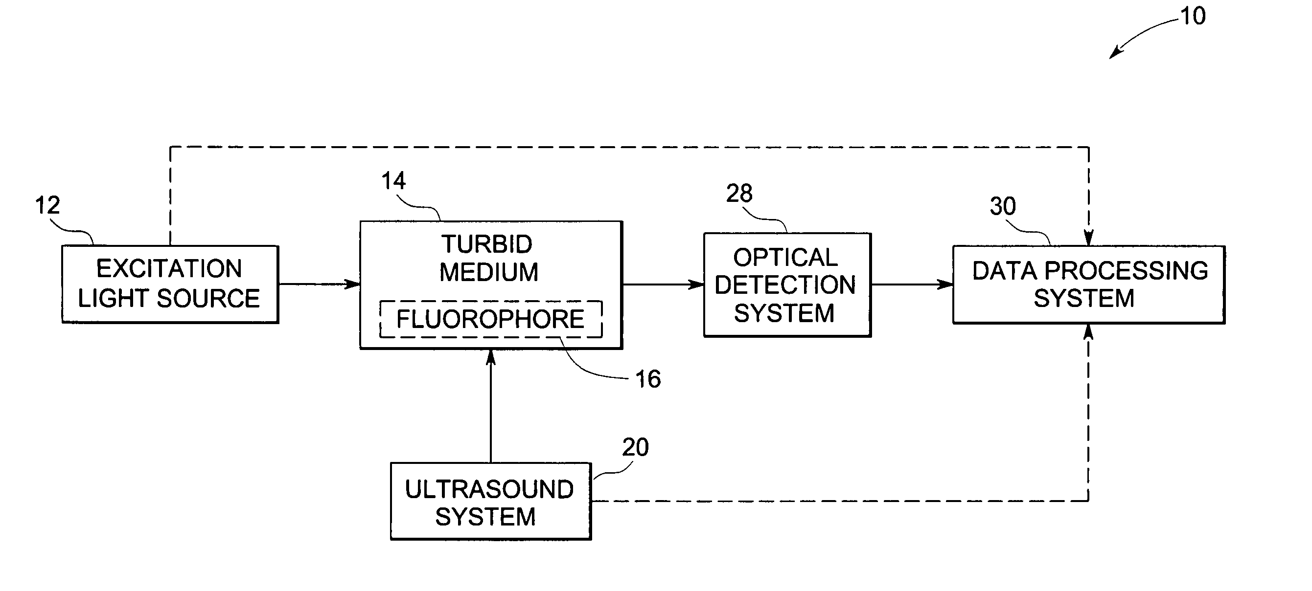
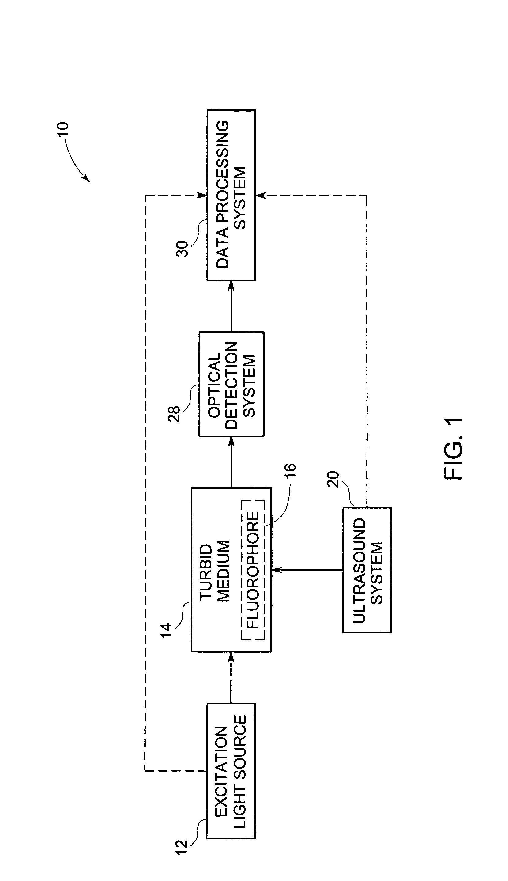
[0023] The present techniques relate to acousto-optic imaging based on localization of fluorescence in a turbid medium (simultaneously absorbing and scattering medium). In various embodiments of the present technique, systems and methods will be employed for localizing an object of interest, e.g., a lesion labeled with a fluorescent dye, in a turbid medium, e.g., biological tissue.

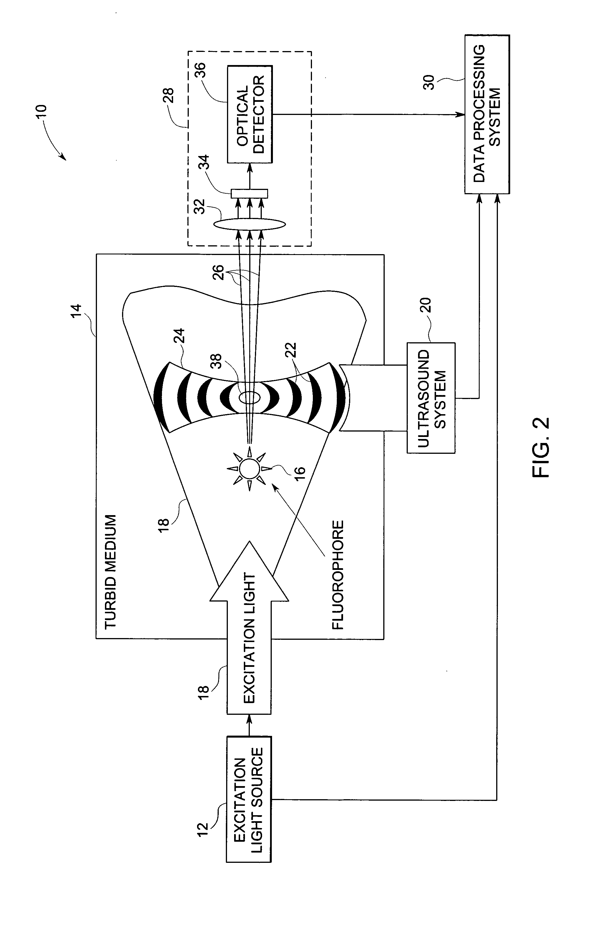
[0024] Referring now to FIG. 1 and FIG. 2, an exemplary acousto-optic imaging system 10 generally includes an excitation light source 12 for illuminating a turbid medium 14, including an object of interest 16, with radiant energy, e.g., light 18. The light 18 excites a fluorophore contrast agent present in the object of interest 16 to cause fluorescence. The system 10 further includes an ultrasound generation system 20 for generating ultrasound pulses or an ultrasonic beam 22 directed into the turbid medium 14, thereby inducing volumetric changes of optical properties of the medium, such as refractive ind...


PUM

PropertyMeasurementUnit
near infrared (NIR) wavelengthsaaaaaaaaaa
wavelengthsaaaaaaaaaa
diameteraaaaaaaaaa

Abstract

A technique is provided for imaging based on localization of fluorescence in a medium. The technique includes illuminating the medium with an excitation light to excite fluorescence, scanning the medium at a plurality of locations via an ultrasonic beam, modulating a portion of the emitted light from the fluorescence via the ultrasonic beam at each of the plurality of locations, differentially detecting the modulated light at a boundary of the medium, and reconstructing an image from the detected signal.

Description

CROSS REFERENCE TO RELATED APPLICATIONS [0001] This application is a Continuation-in-Part of U.S. patent application Ser. No. 10 / 714,734, filed on Nov. 17, 2003, which is herein incorporated by reference.BACKGROUND [0002] The invention relates generally to the field of imaging and more specifically, to the field of acousto-optic imaging. [0003] Various imaging techniques have been developed for use in a wide range of applications. For example, in modern healthcare facilities, non-invasive imaging systems are often used for identifying, diagnosing, and treating physical conditions. Medical imaging typically encompasses the different non-invasive techniques to image and visualize the internal structures and / or functional behavior (such as chemical or metabolic activity) of organs and tissues within a patient. Currently, a number of modalities exist for medical diagnostic and imaging systems, each typically operating on different physical principles to generate different types of image...

Claims


Application Information

Patent Timeline
Patent Type & Authority Applications(United States)
IPC IPC(8): A61B6/00A61B5/00G01N21/17G01N21/47
CPCA61B5/0048A61B5/0091A61B5/4312A61K49/0017A61K49/0032A61K49/0034G01N2021/6439B82Y10/00B82Y20/00G01N21/1717G01N21/4795G01N21/6456G01N2021/1729B82Y5/00A61B5/0051
Inventor FOMITCHOV, PAVEL ALEXEYEVICHKRISHNAN, KAJOLI BANERJEELOMNES, STEPHEN JOHNSONHEUKENSFELDT JANSEN, FLORIBERTUS P. M.
Owner GENERAL ELECTRIC CO
Why Eureka
Try Eureka