Cuff for blood pressure monitor

Inactive Publication Date: 2006-03-16
OMRON HEALTHCARE CO LTD
View PDF17 Cites 7 Cited by
  • Summary
  • Abstract
  • Description
  • Claims
  • Application Information

AI Technical Summary

Benefits of technology

[0017] An object of the present invention is to provide a cuff for a blood pressure monitor permitting a f

Problems solved by technology

The problem at this time is occurrence of wrinkles S1 at the surface of air bag 10J inflated by the pressurized air.
Occurrence of wrinkles S1 leads to degradation of avascularization performance by air bag 10J, disadvantageously decreasing the accuracy in measurement of blood pressure values.
In this case, it will not be possible to sufficiently inflate air bag 10J over the entire region, and thus, the blood pressure values measured will include considerable errors.
With the above-described techniques, however, wrinkles are caused to occur locally in prescribed positions of the air bag, which may rather increase the probability of occurrence of bending in the relevant positions.
If such bending occurs in the air bag, the above-described flow of the air in the inflated/deflated space will be blocked, making it difficult to uniformly inflate the air bag over the entire region.
In such a case, it is not possible to uniformly and stably press the measurement site, leading to occurrence of measurement errors.
The technique is

Method used


Image

  • Cuff for blood pressure monitor
  • Cuff for blood pressure monitor
  • Cuff for blood pressure monitor

Examples


Example

First Embodiment

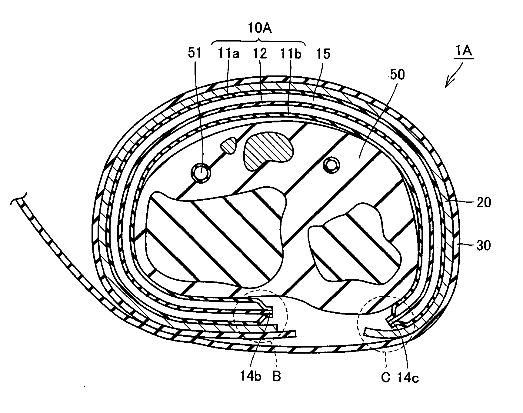
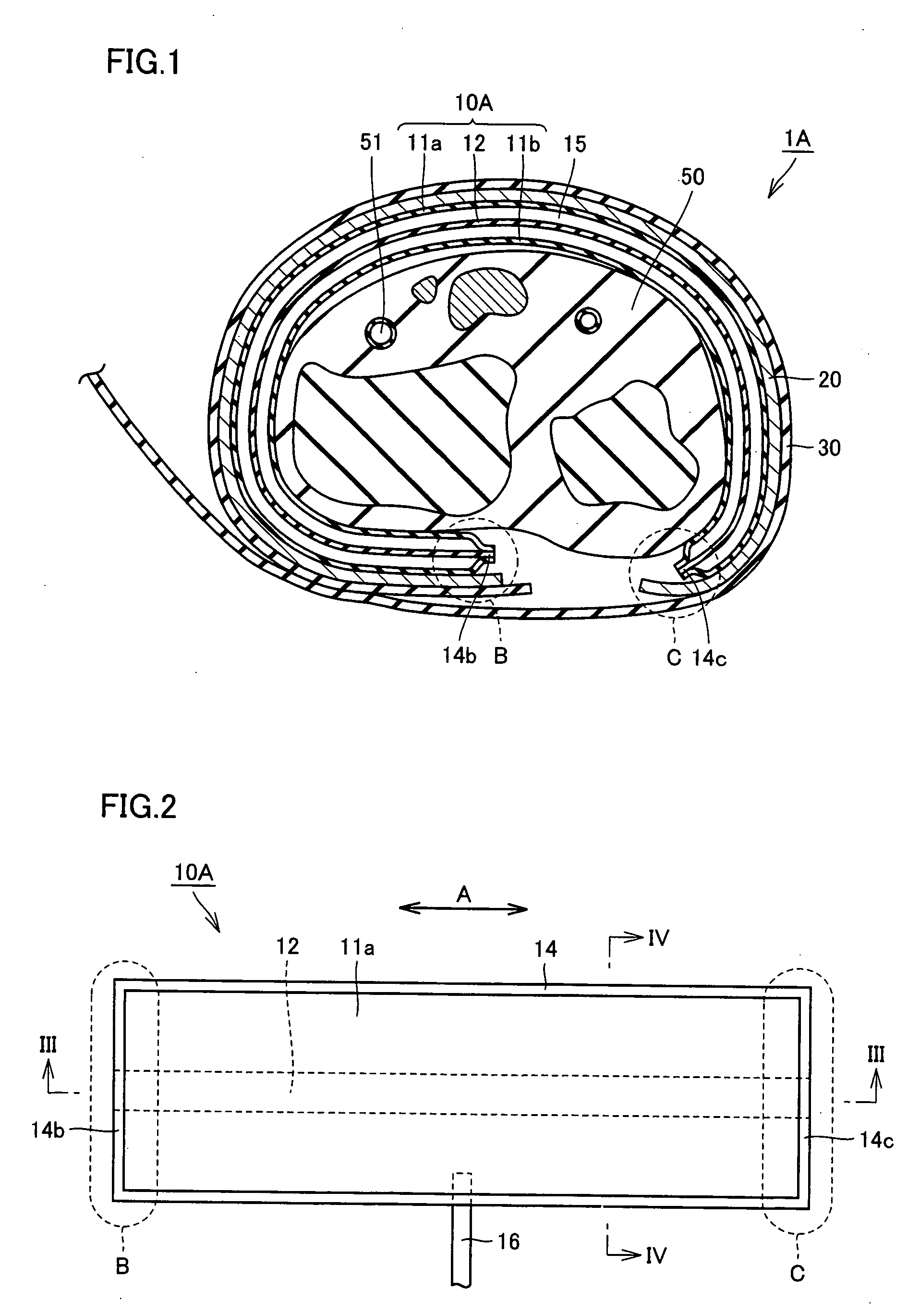
[0050]FIG. 1 is a schematic cross sectional view of a cuff for a blood pressure monitor according to a first embodiment of the present invention, showing the state where the cuff is wound around a wrist. As shown in FIG. 1, the cuff 1A for a blood pressure monitor of the present embodiment includes, among others, an air bag 10A that is a fluid bag, a curled elastic member 20 that is an elastic member located on the outside of air bag 10A and wound in an approximately cylindrical shape radially changeable in size, and a fastening band 30 for securing cuff 1A to the living body. Air bag 10A has its outer peripheral surface fixed to the inner peripheral surface of curled elastic member 20. The outer peripheral surface of curled elastic member 20 is fixed to the inner peripheral surface of fastening band 30.

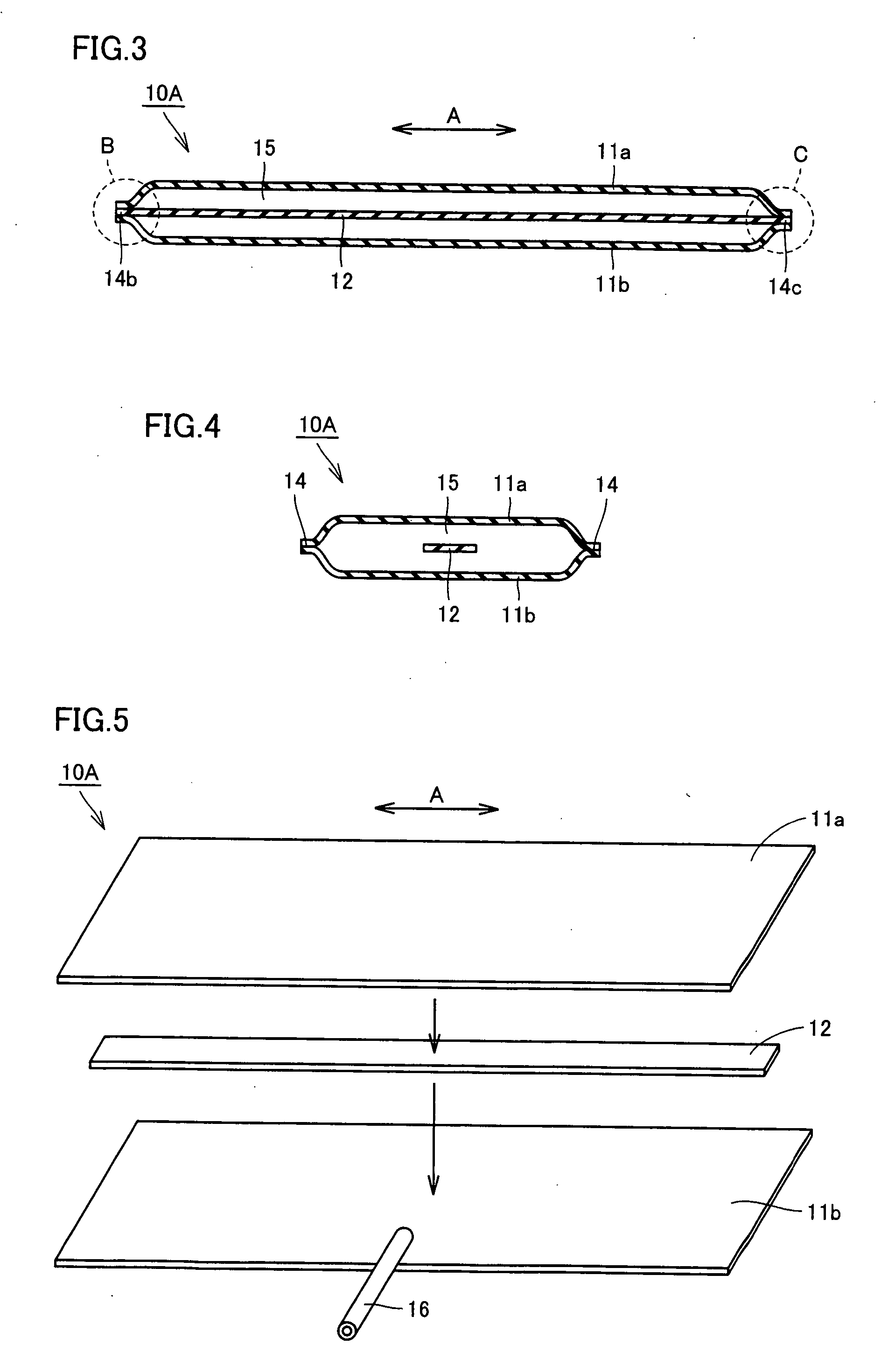
[0051]FIG. 2 is a schematic top plan view showing the air bag in FIG. 1 in a spread state. FIG. 3 is a schematic cross sectional view of the air bag in FIG. 2, take...

Example

Second Embodiment

[0063]FIG. 7 is a schematic cross sectional view of an air bag of a cuff for a blood pressure monitor according to a second embodiment of the present invention, taken along the winding direction of the cuff. FIG. 8 is a schematic cross sectional view of the same air bag taken along the direction orthogonal to the winding direction of the cuff. The cuff for a blood pressure monitor of the present embodiment is identical to the cuff for a blood pressure monitor of the first embodiment except for the configuration of the air bag, and thus, the differences in structure of the air bag will be described in the following. As for the air bag as well, the corresponding portions are denoted by the same reference characters, and description thereof will not be repeated.

[0064] As shown in FIGS. 7 and 8, in the air bag 10B of the cuff for a blood pressure monitor of the present embodiment, as in the case of air bag 10A of cuff 1A for a blood pressure monitor of the first embod...

Example

Third Embodiment

[0071]FIG. 12 is a schematic top plan view showing a structure of an air bag of a cuff for a blood pressure monitor according to a third embodiment of the present invention. The cuff for a blood pressure monitor of the present embodiment is identical to the cuff for a blood pressure monitor of the first embodiment except for the configuration of the air bag. Thus, in the following, only the differences in structure of the air bag will be described. In the air bag as well, the corresponding portions are denoted by the same reference characters, and description thereof will not be repeated.

[0072] As shown in FIG. 12, in the air bag 10E of the cuff for a blood pressure monitor of the present embodiment, as in the case of air bag 10A of cuff 1A for a blood pressure monitor of the first embodiment, a band-shaped connecting portion 12 is arranged inside an inflated / deflated space 15 formed by an outer wall portion 11a and an inner wall portion 11b. However, band-shaped c...


PUM


Abstract

A cuff for a blood pressure monitor is wound around a measurement site of the living body, and includes an air bag having an inflated/deflated space formed therein by melting and bonding rims of an outer wall portion and an inner wall portion together. The air bag contains a band-shaped connecting portion, which has ends respectively attached to one end and the other end of the air bag in its winding direction around the living body, so as to extend substantially continuously from the one end to the other end of the air bag. The band-shaped connecting portion is arranged inside the inflated/deflated space of the air bag. With this configuration, a cuff for a blood pressure monitor permitting uniform inflation of the air bag over the entire region when the pressurized air is introduced therein is obtained.

Description

BACKGROUND OF THE INVENTION [0001] 1. Field of the Invention [0002] The present invention relates to a cuff for a blood pressure monitor wound around a measurement site of a living body, such as a wrist, an upper arm or the like, for measurement of blood pressure values. [0003] 2. Description of the Background Art [0004] To measure a blood pressure value, generally, a cuff provided with a fluid bag for pressing an artery located within a living body is wound around the body surface, and arterial pressure pulse waves caused in the artery by inflation / deflation of the fluid bag are detected to measure the blood pressure value. Here, the cuff refers to a band-shaped structure having a bladder, which can be wound around a part of a living body, for use in measurement of arterial pressure of an upper limb, a lower limb or the like by introducing fluid such as gas or liquid into the bladder. Thus, the cuff represents the concept including the fluid bag as well as members for winding the f...

Claims


Application Information

Patent Timeline
IPC IPC(8): A61B5/02
CPCA61B5/02233A61B5/022
Inventor KISHIMOTO, HIROSHISANO, YOSHIHIKOKARO, HIROMICHI
Owner OMRON HEALTHCARE CO LTD
Why Eureka
Try Eureka