Coiled ladder stent

a ladder stent and stent technology, applied in the field of ladder stent rungs, can solve the problems of ladder stent failure, rails or rungs, repeated flexion, compression, extension or torsion of the stent, and the failure of the conventional ladder stent under the severe mechanical manipulation environment, so as to reduce or minimize the negative consequences of the rung failure, reduce the strength, and reduce the effect of strength

Inactive Publication Date: 2006-03-16
LEMAITRE VASCULAR
View PDF20 Cites 97 Cited by
  • Summary
  • Abstract
  • Description
  • Claims
  • Application Information

AI Technical Summary

Benefits of technology

[0013] One feature of the invention is the recognition of the need to design ladder stents so that the rungs and rails are unlikely to fail, but if either of the rungs or rails is to fail, it is the rung, not the rail, that is the preferred failure mode. Another feature of the invention is the recognition of the need to design ladder stents so that if a rung does fail, it fails at a location that reduces or minimizes any negative consequences from the rung failure. Such locations will generally be referred to as fail safe or fracture safe locations.
[0014] A first aspect of the present invention is directed to a coiled ladder stent comprising first and second rails and rungs connecting the rails. At least a first rung comprises a lower strength portion. The lower strength portion is positioned at a reduced strength fracture location along the first rung so to promote any fracture of the ladder stent at the fracture location along the rung to help prevent fracture of a rail.
[0016] A second aspect of the invention is directed to a coiled ladder stent comprising first and second rails and rungs connecting the rails. At least a first rung is an enhanced flexibility rung that helps to accommodate relative movement between the first and second rails. Doing so helps to prevent fracture of the rails and rungs.

Problems solved by technology

Other locations, such as femoro-popiliteal arteries, coronary arteries, and sub-clavian arteries / veins, subject a stent to relatively severe mechanical manipulation environments and cause the stent to repeatedly undergo flexion, compression, extension, or torsion, or a combination thereof.
It has been found that the rails or the rungs, of conventional ladder stents may fail under the severe mechanical manipulation environments.
The competing demands of flexibility, strength, durability and biocompatibility create significant obstacles to the design of ladder stents.

Method used


Image

  • Coiled ladder stent
  • Coiled ladder stent
  • Coiled ladder stent

Examples


Embodiment Construction

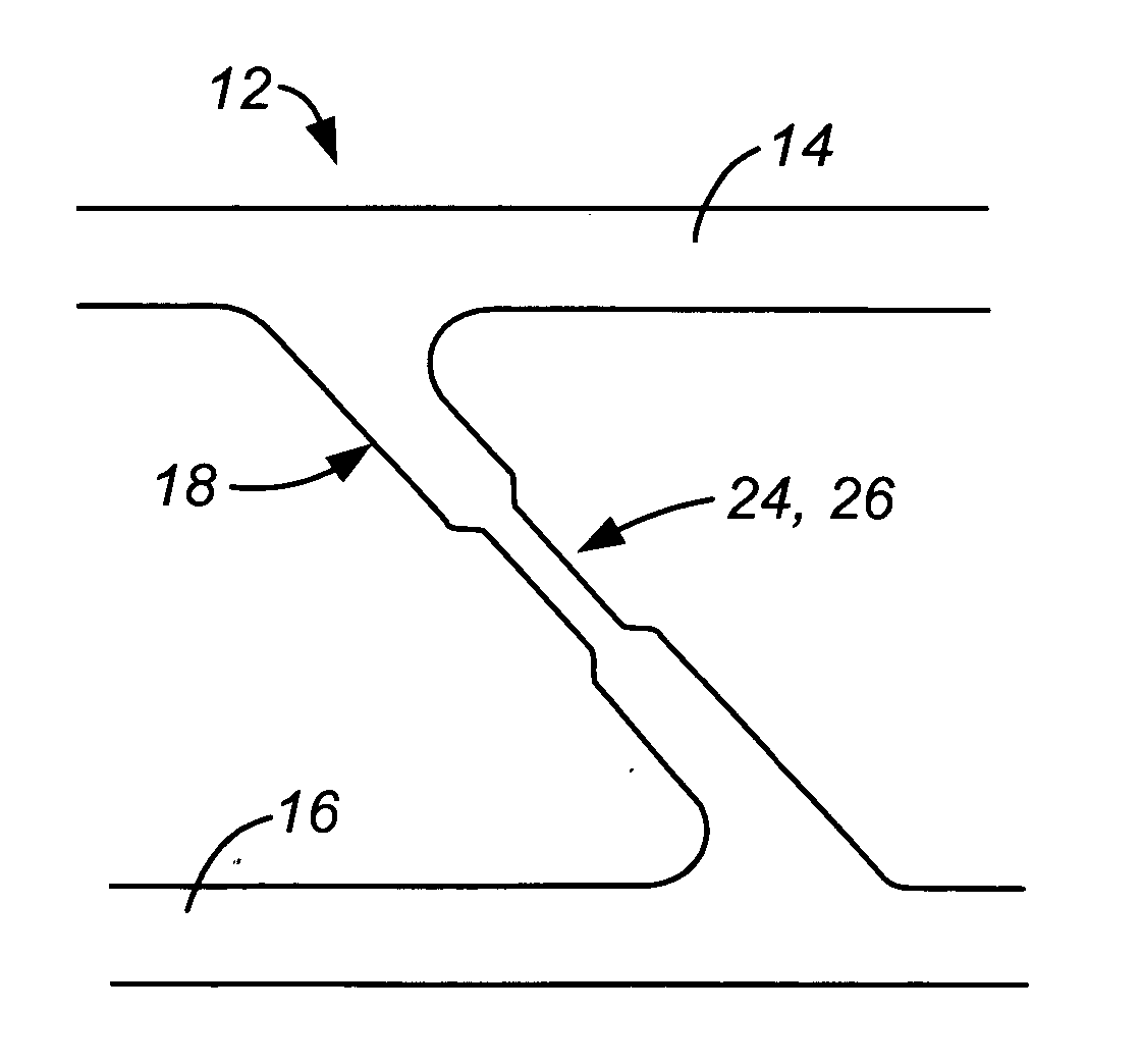
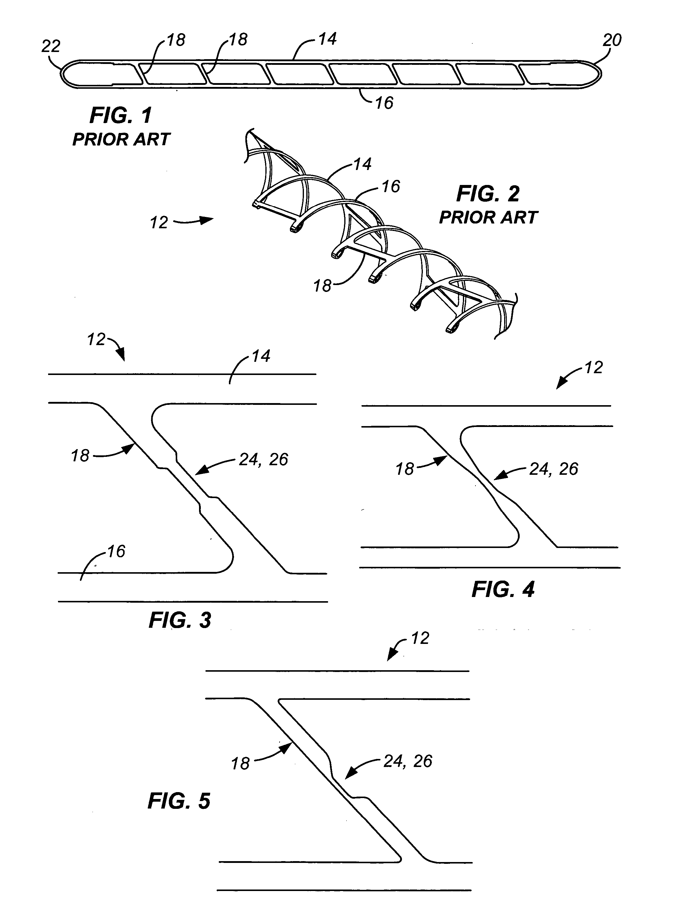
[0025]FIG. 1 illustrates a conventional ladder stent blank 10 from which a conventional ladder stent 12, shown in FIG. 2, is formed. Each of ladder stent hank 10 and ladder stent 12 has rails 14, 16 and rungs 18 connecting the rails. Also, rails 14, 16 join together at their distal ends 20, 22. Stent 12 is chemically photoetched from a flat sheet of material (dimensions appropriate for desired final stent size), heat shape set on a mandrel to a helical / coiled form and then surface treated to final product dimension and form.

[0026] Rungs 18 are preferably oriented at an acute angle to rails 14 so that when ladder stent 12 is wound down onto a delivery catheter, or other delivery device, rungs 18 are oriented generally parallel to the delivery device axis. This provides a smoother appearance and thus aids passage through the vasculature and to the target site. This feature is further discussed in U.S. Pat. No. 6,660,032.

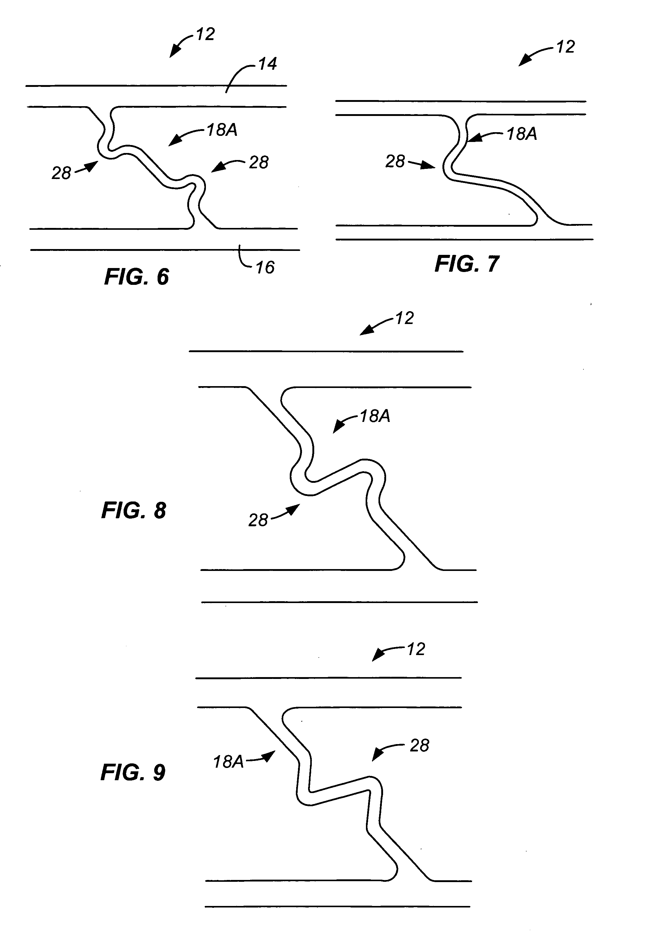
[0027]FIGS. 3-12 are enlarged views of sections of several embo...


PUM


Abstract

A coiled ladder stent comprises first and second rails and rungs connecting the rails. At least one rung has lower strength portion or is an enhanced flexibility rung, or both. The lower strength portion is positioned at a reduced strength fracture location along the rung so to promote any fracture of the ladder stent at the fracture location along the rung to help prevent fracture of a rail. One way to make the lower strength portion is to make the cross-sectional area of the lower strength portion less than the average cross-sectional area of the rung. The enhanced flexibility aspect helps to accommodate relative movement between the first and second rails. Doing so helps to prevent fracture of the rails and rungs. In some embodiments of the invention the enhanced flexibility rung comprises one or more nonlinear, such as generally S-shaped or generally U-shaped, portions.

Description

CROSS-REFERENCE TO OTHER APPLICATIONS [0001] None. FEDERALLY SPONSORED RESEARCH OR DEVELOPMENT [0002] None. BACKGROUND OF THE INVENTION [0003] The present invention is directed to the rungs of a ladder stent. [0004] Stents, covered stents and other endoluminal prostheses are often useful for placement in various-hollow body structures, such as blood vessels, including coronary arteries, iliac arteries and femoro-popiliteal arteries, the ureter, urethra, bronchus, biliary tract, gastrointestinal tract and the like, for the treatment of conditions which may benefit from the introduction of a reinforcing or protective structure and / or the introduction of a therapeutic agent within the body lumen. The prostheses will typically be placed endoluminally. As used herein, “endoluminally” will mean placement by percutaneous or cutdown procedures, wherein the prosthesis is transluminally advanced through the body lumen from a remote location to a target site in the lumen. In vascular procedure...

Claims


Application Information

Patent Timeline
Patent Type & Authority Applications(United States)
IPC IPC(8): A61F2/06
CPCA61F2/88A61F2002/9155A61F2/915A61F2/91
Inventor OLSON, JONATHAN M.ROSARIO, PETER E.RAVICHANDRAN, GURUSWAMITSURUDA, MARSHALL
Owner LEMAITRE VASCULAR
Why Eureka
Try Eureka