Tool

a technology for hip replacement and tools, applied in the field of tools, can solve the problems of reshaping of bone, and affecting the accuracy of angled angles

Inactive Publication Date: 2006-03-16
FINSBURY DEV
View PDF20 Cites 224 Cited by
  • Summary
  • Abstract
  • Description
  • Claims
  • Application Information

AI Technical Summary

Benefits of technology

[0031] The foregoing arrangement is suitable where the acetabular cup prosthesis does not include a peg extending from the external surface of the prosthesis. In this arrangement, once the trial cup is removed, the acetabular cup prosthesis is brought into position using a surgical tool in

Problems solved by technology

Diseases such as rheumatoid- and osteo-arthritis can cause erosion of the cartilage lining of the acetabulum so that the ball of the femur and the hip bone rub together causing pain and further erosion.
Bone erosion may cause the bones themselves to attempt to compensate for the erosion which may result in the bone being reshaped.
This misshapen joint may cause pain and may eventually cease to function altogether.
This is particularly important since incorrect positioning of the acetabular component can lead to the prosthetic hip joint suffering from dislocations, a decreased range of motion and possibly eventual loosening or failure of both components of the joint.
However, despite all care having been taken, the orientation of the cup in the replaced hip can deviate from the ideal.
As the position to be judged is a compound angle, it is particularly difficult to visualise.
Second as the natural face of the acetabulum is not uniform and where the hip is arthritic may be distorted by osteophites, t

Method used


Image

  • Tool
  • Tool
  • Tool

Examples


Embodiment Construction

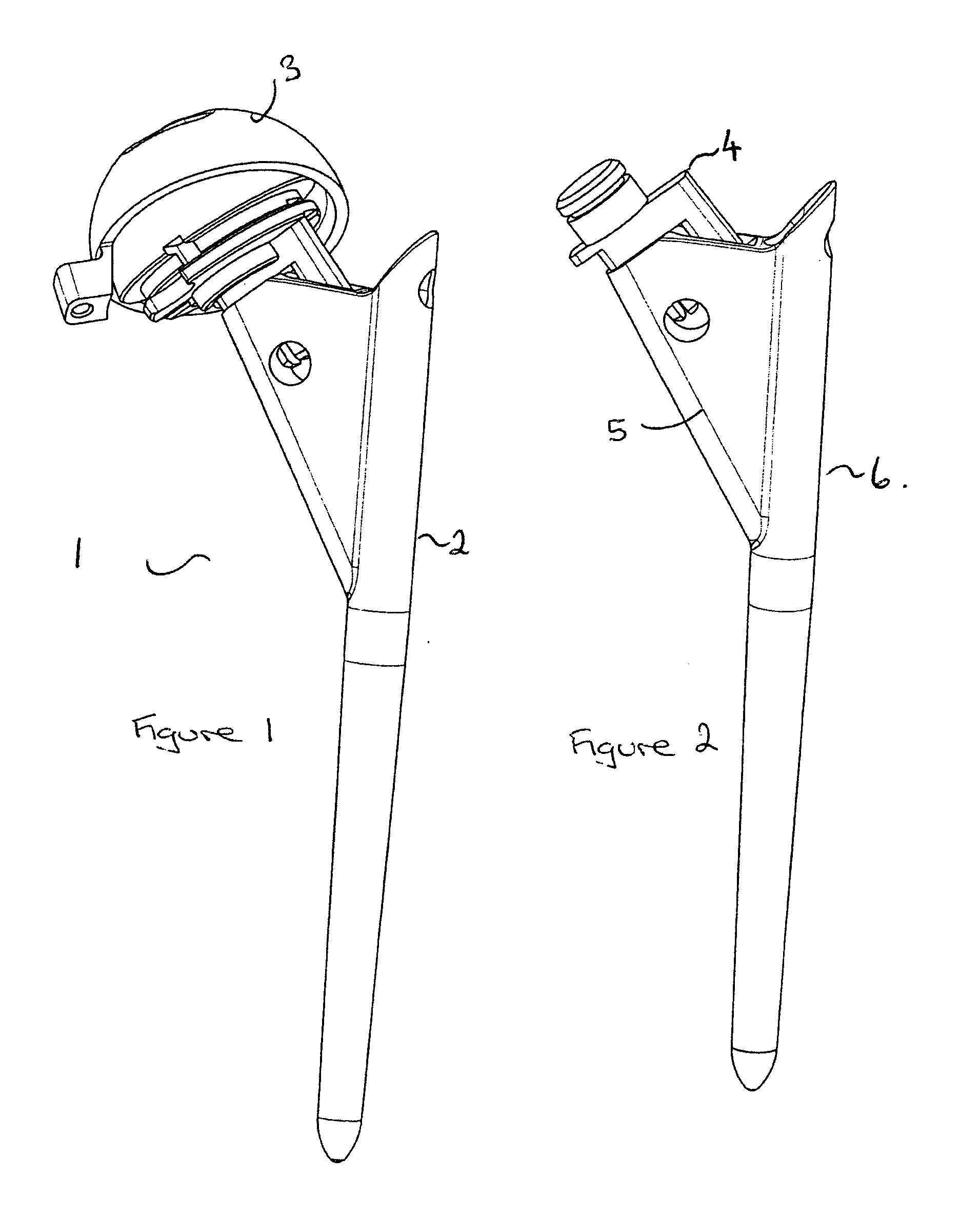
[0052] As illustrated in FIG. 1, one arrangement of the alignment trial system 1 of the present invention comprises a trial femoral prosthesis 2 and a trial acetabular cup prosthesis 3. The trial femoral prosthesis is modular and two components are shown in FIG. 2. Here a first neck component 4 is inserted in a side arm 5 of the stem component 6.

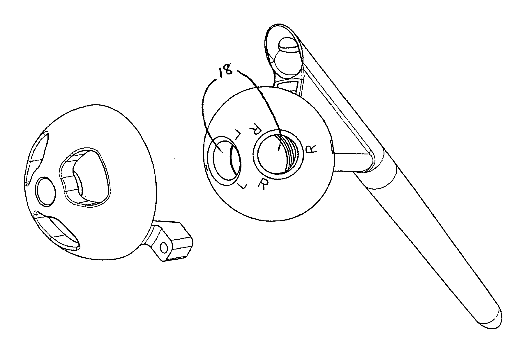
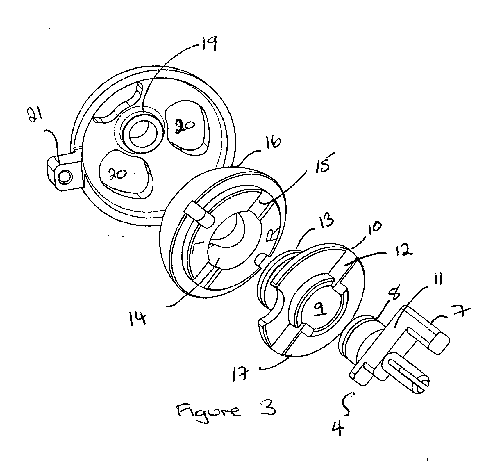
[0053] The first neck component 4 can be seen more clearly in FIG. 3. It includes a flag 7 which when inserted between the walls of the side arm 5 and prevents the rotation of the component. A collar 8 extends upwardly therefrom to interlock with a corresponding aperture 9 in the second neck component 10. When the collar 8 is inserted into the hole 9 and locked in place, the arm 11 of the first neck component will sit in groove 12 such that mutual rotation of first and second neck components cannot occur. A collar 13 extends upwardly to interlock with the corresponding aperture 14 in the head component 16.

[0054] A groove 15 in the undersid...


PUM


Abstract

An alignment trial system for a hip prosthesis comprising: (a) a trial femoral prosthesis comprising a head component, a neck component and a stem component; and (b) a trial acetabular cup prosthesis wherein the head component of the trial femoral prosthesis and the trial acetabular cup prosthesis include interlocking engagement formations and wherein the trial acetabular cup prosthesis includes means to facilitate the formation of a bore in the pelvis. The invention also relates to a method of inserting an acetabular cup prosthesis comprising the steps of: (I) preparing the femur and pelvis for insertion of a femoral prosthesis and an acetabular cup prosthesis; (ii) inserting the alignment trial apparatus of the above first aspect such that the trial femoral prosthesis is located in the prepared femur; (iii) locating the patient's hip such that the trial cup prosthesis is seated in the prepared portion of the pelvis; (v) drilling a bore in the pelvis; (vi) removing the alignment trial apparatus; (vii)inserting the acetabular cup prosthesis into the pelvis using the mark as a guide.

Description

BACKGROUND OF THE INVENTION [0001] The present invention relates to a tool for use in total hip replacement surgery resurfacing operations. More particularly, it relates to an acetabular trial system for use in total hip replacement surgery; a tool for positioning an acetabular cup and a method of carrying out total hip replacement surgery. Most particularly, it relates to a trial system which will assist the surgeon to determine the placement angles to enable the acetabular component of the hip prosthesis to be positioned at the optimal angle. [0002] The efficient functioning of the hip joints is extremely important to the well being and mobility of the human body. Each hip joint is comprised by the upper portion of the femur which terminates in an offset bony neck surmounted by a ball-headed portion, known as the femoral head, which rotates within a socket, known as the acetabulum, in the pelvis. Diseases such as rheumatoid- and osteo-arthritis can cause erosion of the cartilage l...

Claims


Application Information

Patent Timeline
IPC IPC(8): A61F2/32A61F2/46A61B17/90A61B17/17A61B19/00A61F2/00A61F2/02A61F2/34A61F2/36
CPCA61B17/1746A61F2250/0089A61F2/32A61F2/3662A61F2/4609A61F2/4684A61F2002/30538A61F2002/30604A61F2002/30708A61F2002/30714A61F2002/3401A61F2002/343A61F2002/3432A61F2002/3611A61F2002/3625A61F2002/4677A61F2250/0006A61F2250/006A61F2250/0084A61B2019/446A61B90/94A61F2002/3071
Inventor WOZENCROFT, ROBERT MICHAEL
Owner FINSBURY DEV
Why Eureka
Try Eureka