
Curved extrusions and method of forming the same

Inactive Publication Date: 2006-03-23
THE BOEING CO
View PDF3 Cites 20 Cited by
  • Summary
  • Abstract
  • Description
  • Claims
  • Application Information

AI Technical Summary

Benefits of technology

[0008] The present invention provides curved extrusions that are free of residual stress, extrusions that have local changes of the cross-section, and a method for forming extrusions to contour without inducing residual stress. The present invention further provides large titanium and titanium alloy extrusions formed to contour that are suitable for, but not limited to, applications in the aerospace industry. The present invention still further provides a method for forming extrusions without inducing residual stress.

Problems solved by technology

Despite the increased usage and production of titanium and its alloys, they are expensive when compared to many other metals and alloys, for example, aluminum and its alloys, because of the complexity of the extraction process, difficulty of melting, and problems during fabrication and machining.
However, disadvantages of extrusions include that extrusions have generally a constant cross-section and that extrusions are straight (as shown in FIGS. 1a and 1b). FIG. 1a provides a cross-sectional view of a typical prior art straight extrusion 10 shown in FIG. 1b.
Extrusions may be formed to contour as a finishing operation, but the forming process may induce high residual stress in the extrusion and may result in loose tolerances, which are both undesirable.
High residual stress of the extrusion may further result in distortion during machining.
Since the curving process would induce residual stress within large extrusions, such as the T-chord, distortion of the extrusion may become a problem for assembling the T-chord.
However, these technologies have the disadvantage that the number and size of the components formed is limited and that production of components is costly.

Method used


Image

  • Curved extrusions and method of forming the same
  • Curved extrusions and method of forming the same
  • Curved extrusions and method of forming the same

Examples


Embodiment Construction

[0030] The following detailed description is of the best currently contemplated modes of carrying out the invention. The description is not to be taken in a limiting sense, but is made merely for the purpose of illustrating the general principles of the invention, since the scope of the invention is best defined by the appended claims.

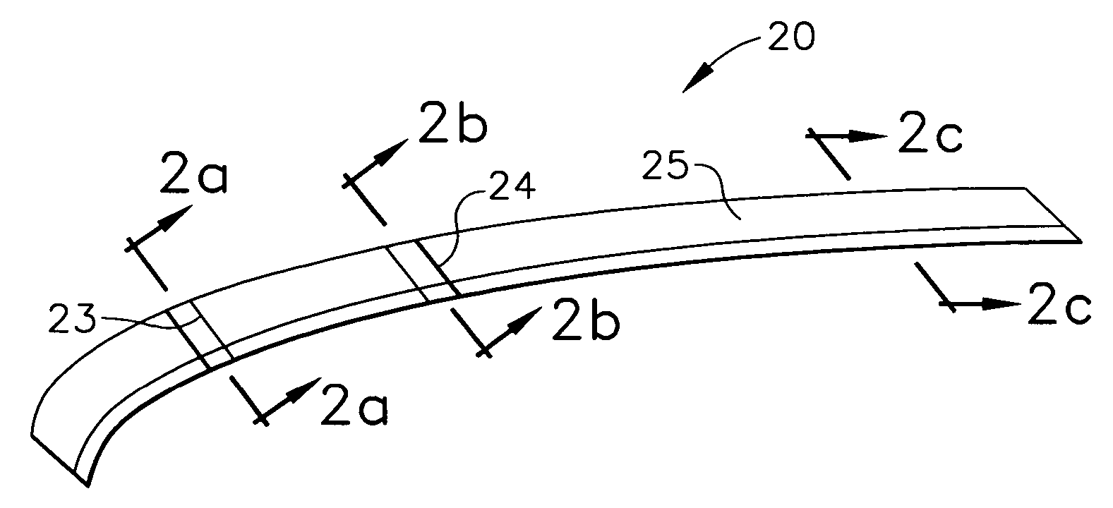
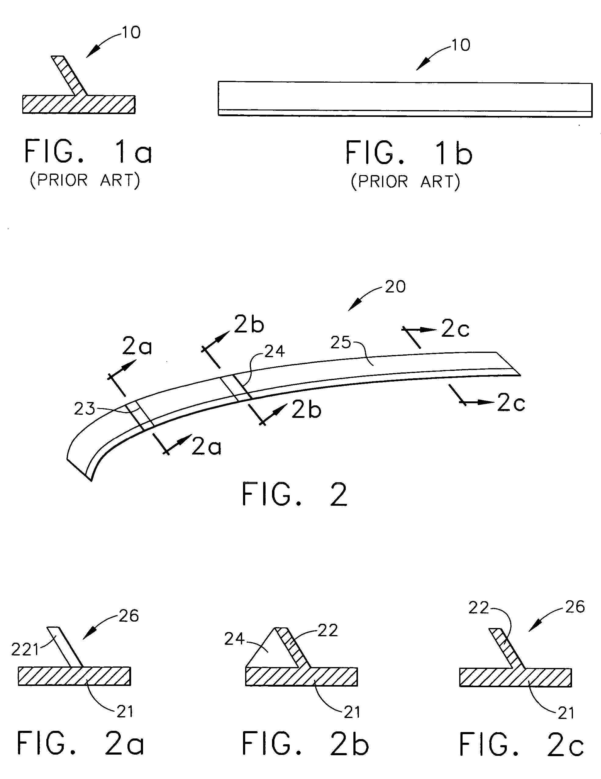
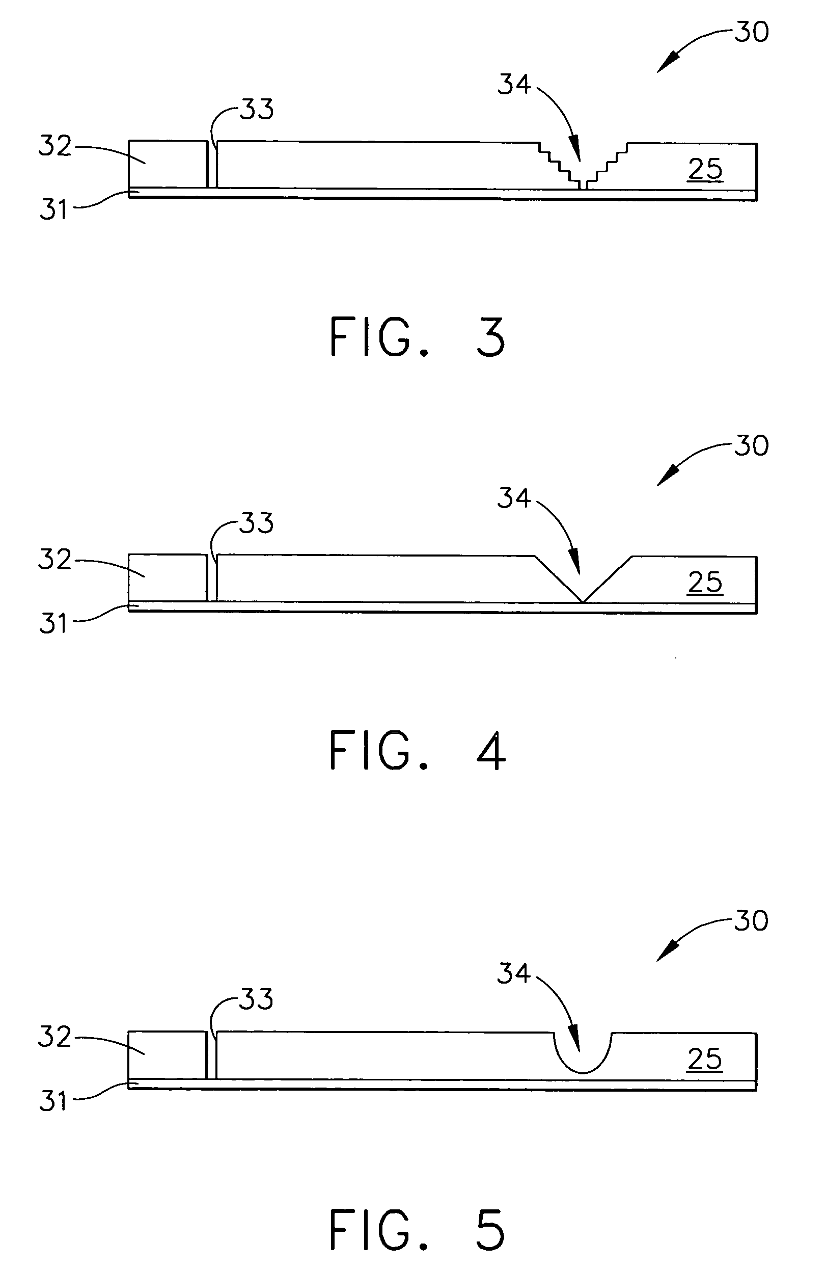
[0031] Broadly, an embodiment of the present invention provides a curved extrusion that is free of residual stress. Contrary to the known prior art, the extrusion as in one embodiment of the present invention includes channels cut into one leg of the extrusion prior to forming the extrusion to contour in order to prevent residual stress. The curved extrusion as in one embodiment of the present invention may be used, for example, in the aerospace industry. By using the method for forming a curved extrusion as in one embodiment of the present invention it will be possible to manufacture large extrusions that are free of residual stress and that may be f...


PUM

PropertyMeasurementUnit
Timeaaaaaaaaaa
Lengthaaaaaaaaaa
Residual stressaaaaaaaaaa

Abstract

A curved extrusion includes a body that has indefinite length and a cross-section, and that is formed to contour and at least one channel cut into the cross-section that is filled with deposited material such that said cross-section of said body is restored. By cutting the channels into the cross-section of the extrusion, the extrusion may be easily formed onto a contoured tool to be curved with lower forming and residual stresses and distortion. By filling the channels with deposited material, the original cross-section and strength of the extrusion can be restored. By adding a transverse stiffener, the strength of the original extrusion may not only be restored but also further improved. By depositing material to create structural features the cross-section of the extrusion may be locally changed. The method for forming curved extrusions of the present invention may be used, for example, to produce T-chords of an aircraft.

Description

BACKGROUND OF THE INVENTION [0001] The present invention generally relates to extrusions and, more particularly, to curved extrusions that are free of residual stress and to a method for forming a curved extrusion with reduced forming and stresses. [0002] The requirements for material used in the aerospace industry are numerous. Demands include improved toughness, lower weight, as well as increased resistance to fatigue and corrosion. The boundaries of material properties are being constantly extended as manufacturers strive to give the next generation of aircraft improved performance while making them more efficient. Titanium and its alloys are increasingly used in the aerospace industry because of their excellent combination of high specific strength (strength-to-weight ratio), which may be maintained at elevated temperature, their fracture resistant characteristics, and their exceptional resistance to corrosion. The titanium alloy currently most commonly used is the alpha-beta al...

Claims


Application Information

Patent Timeline
IPC IPC(8): E04C2/38
CPCB21C23/002B23K26/34B23K35/0244B23K26/322B23K35/325B23P15/00B23K26/32B23K2103/14B21C23/00
Inventor MACDONALD-SCHMIDT, TRACYSLATTERY, KEVIN T.
Owner THE BOEING CO
Features
  • Generate Ideas
  • Intellectual Property
  • Life Sciences
  • Materials
  • Tech Scout
  • Unparalleled Data Quality
  • Higher Quality Content
  • 60% Fewer Hallucinations
Learn More