Air conditioner control logic for compressor noise and torque management

a technology of compressor noise and torque management, applied in the field of air conditioner control system, can solve the problems of affecting the performance of the vehicle, the noise and vibration of the compressor, and so as to reduce the torque requirement of the compressor, reduce the noise of the compressor, and facilitate the operation at start-up.

Active Publication Date: 2006-03-23
NISSAN MOTOR CO LTD
View PDF12 Cites 14 Cited by
  • Summary
  • Abstract
  • Description
  • Claims
  • Application Information

AI Technical Summary

Benefits of technology

[0008] One object of the present invention is to provide an air conditioner with control logic that is quieter and / or easier to operate at start up. In other words, the air conditioner of the present invention was basically contrived to avoid to the greatest extent possible the adverse effects of the compressor being started, e.g., minimizes the refrigerant noises at compressor start up and / or decrease the compressor torque requirements due to slugging at compressor start up.

Problems solved by technology

When the compressor of an air conditioner is first started, the rapid pressure changes that occur with the compressor cycling from OFF to ON can create various sounds and vibrations that may be unpleasant to humans.
This increase in the compressor torque requirement can have an adverse affect on the performance of the vehicle.

Method used


Image

  • Air conditioner control logic for compressor noise and torque management
  • Air conditioner control logic for compressor noise and torque management
  • Air conditioner control logic for compressor noise and torque management

Examples


first embodiment

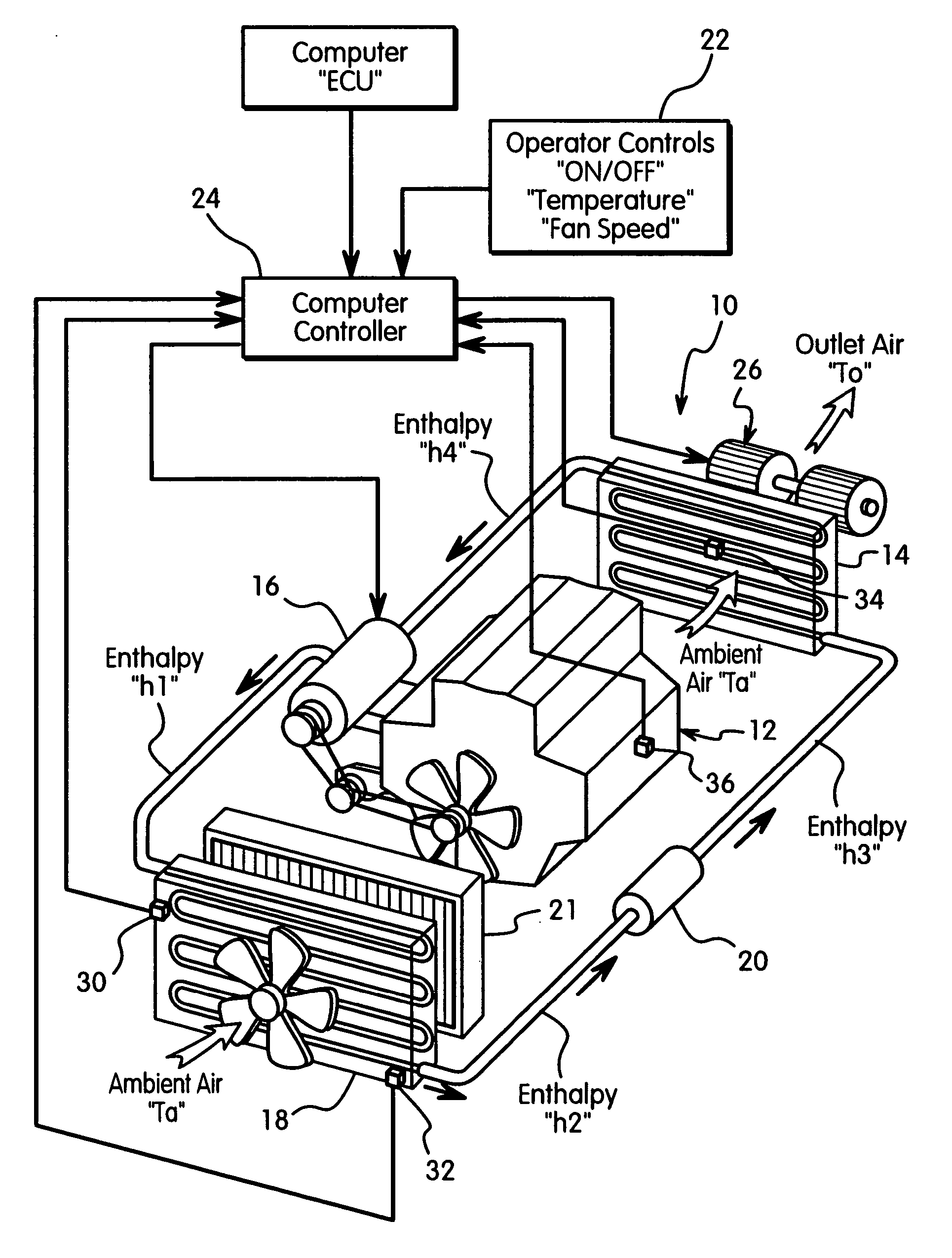
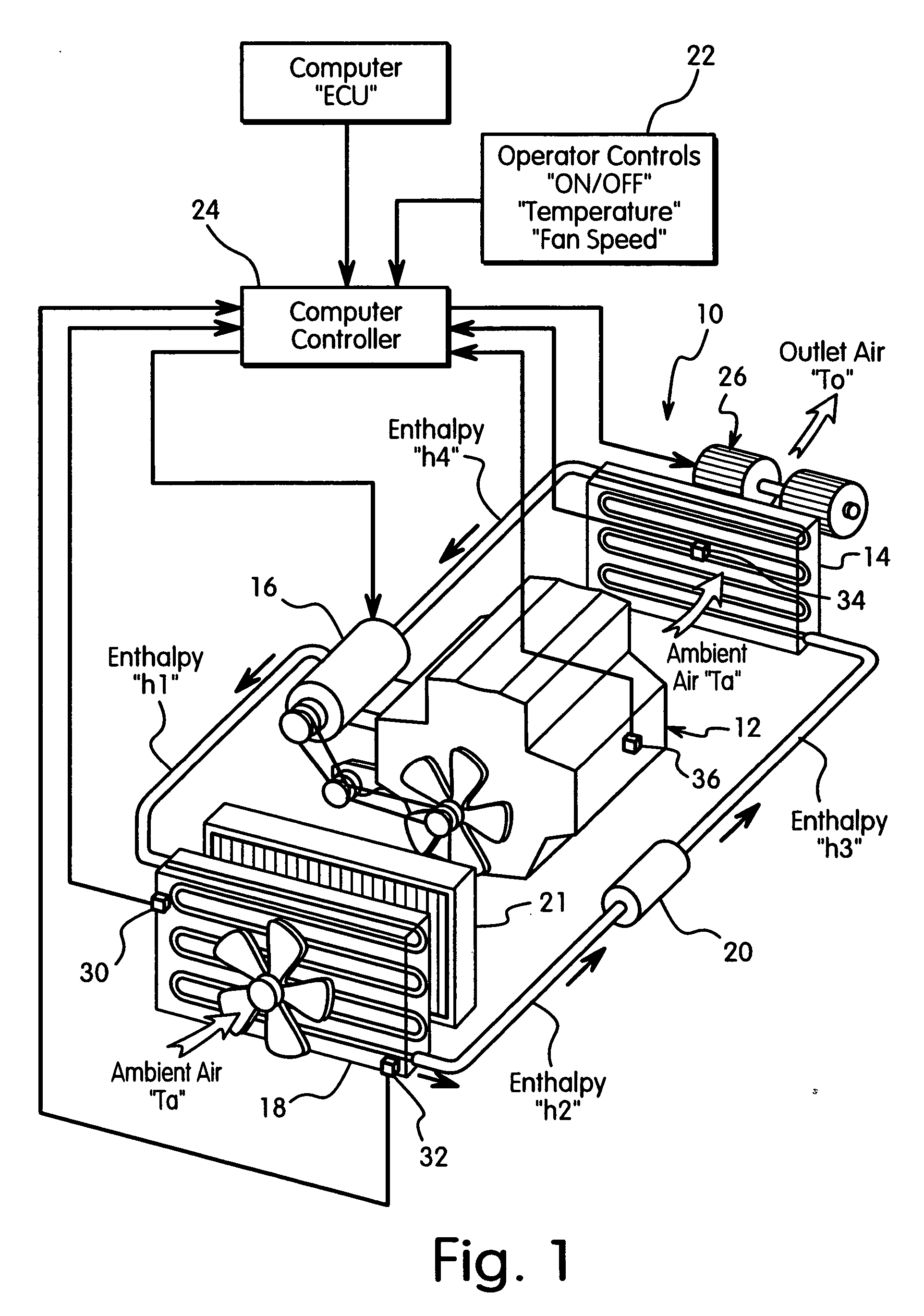
[0020] Referring initially to FIG. 1, an air conditioner 10 is illustrated in accordance with the present invention. The air conditioner 10 according to the present invention is particularly suitable for an automobile or other passenger vehicle (such as but not limited to a car, an SUV, a minivan, a station wagon, a pick-up truck, etc.,) as well as refrigeration systems for homes and industrial use. In the illustrated embodiment, the air conditioner 10 is driven by a vehicle engine 12 in a conventional manner. Basically, the air conditioner 10 has a refrigerant circuit that includes an evaporator 14, a compressor 16 with an electromagnetic clutch, a condenser 18 and an expansion valve or orifice 20. Typically, the condenser 18 is located in front of a radiator 21 that cools the engine coolant of the engine 12. These components 14, 16, 18 and 20 are conventional components that are well known in the air conditioning field. Since these components 14, 16, 18 and 20 are well known in th...

second embodiment

[0070] Now referring to FIGS. 6 and 7, a one time pulsing logic in accordance with the present invention will now be discussed. The control logic illustrated in FIGS. 6 and 7 are utilized separately from the prior full time pulsing logic. The control logic of FIGS. 6 and 7 is directed to minimize the noise due to slugging and / or manage the torque load on the engine due to the liquid refrigerant in the compressor 16. Thus, after, the initial pulsing or cycling of the compressor 16, the air conditioner 10 is operated according to the normal control logic of FIG. 4.

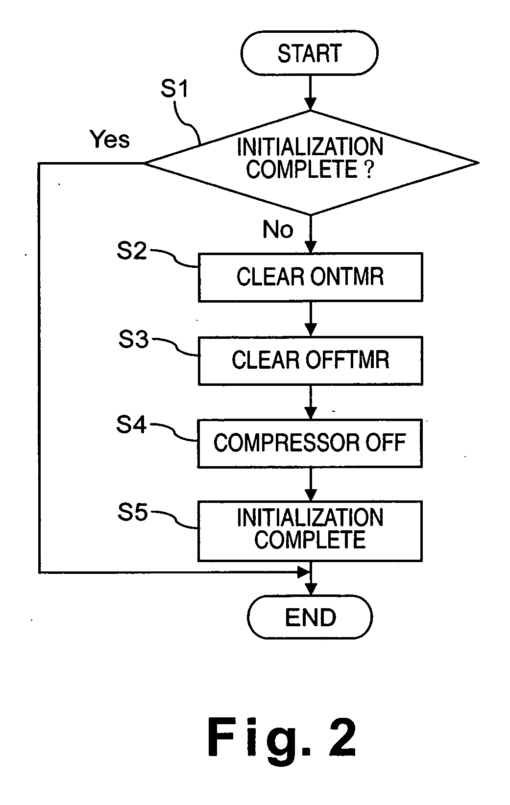
[0071] Referring initially to the initialization logic of FIG. 6, basically, the initialization control logic of FIG. 6 is identical to the initialization control logic of FIG. 2, except that additional steps have been added such that pulsing of the compressor 16 between ON and OFF operating states only occurs when the engine 12 is cold and when there is a possibility of liquid refrigerant accumulating in the compressor 16. ...


PUM


Abstract

An air conditioner has a controller that controls the operation of a refrigerant circuit that has a compressor, a condenser, an expansion valve or orifice tube, and an evaporator. The condenser receives a compressed refrigerant from the compressor and condenses the refrigerant to either a liquid phase or a saturated liquid-vapor phase. The condensed refrigerant is then passed through the expansion valve or orifice tube to expand the refrigerant and to delivery the refrigerant to the evaporator. When the compressor is first started, various sounds and vibrations are created that may be unpleasant to humans. Also, if the engine is cold, then the compressor may have liquid refrigerant that can increase the torque needed to start the compressor. The controller pulses the compressor between ON and OFF operating states to reduce or eliminate these sounds and / or manage the start up torque of the compressor.

Description

BACKGROUND OF THE INVENTION [0001] 1. Field of the Invention [0002] The present invention generally relates to an air conditioner. More specifically, the present invention relates to an air conditioner control system for reducing refrigerant noise and for managing torque, during initial engagement of a compressor of the air conditioner. [0003] 2. Background Information [0004] A typical automobile air conditioner includes a compressor, a condenser, an expansion valve or orifice tube, and an evaporator. The compressor compresses a cool vapor-phase refrigerant (e.g., Freon, R134a) to heat the same, resulting in a hot, high-pressure vapor-phase refrigerant. This hot vapor-phase refrigerant runs through a condenser, typically a coil that dissipates heat. The condenser condenses the hot vapor-phase refrigerant into liquid refrigerant. The liquid refrigerant is throttled through an expansion valve, which evaporates the refrigerant to a cold, low-pressure saturated liquid-vapor-phase refrig...

Claims


Application Information

Patent Timeline
Patent Type & Authority Applications(United States)
IPC IPC(8): G05D23/32F25B1/00F25B49/00F28D1/00F28F13/00F25D19/00
CPCB60H1/3216B60H2001/006B60H2001/3251B60H2001/3255B60H2001/3263F25B2600/0251B60H2001/327B60H2001/3282F25B49/022F25B2500/12F25B2500/26B60H2001/3266
Inventor EISENHOUR, RONALD S.
Owner NISSAN MOTOR CO LTD
Why Eureka
Try Eureka