Starting apparatus
a technology of starting apparatus and starting gear, which is applied in the direction of engine starters, machines/engines, power operated starters, etc., can solve the problems of large physical configuration of the motor, unconstant reaction force applied to the internal gear, and unpleasant sound likely to be caused in the engine start-up process, etc., and achieves simple structure and reduce vibration
- Summary
- Abstract
- Description
- Claims
- Application Information
AI Technical Summary
Benefits of technology
Problems solved by technology
Method used
Image
Examples
first embodiment
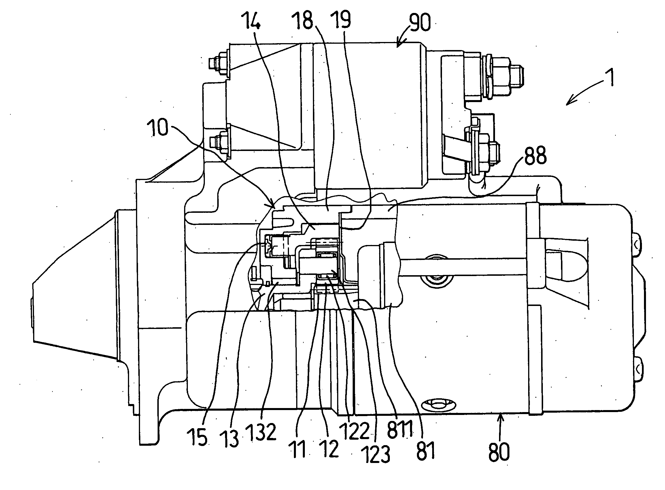
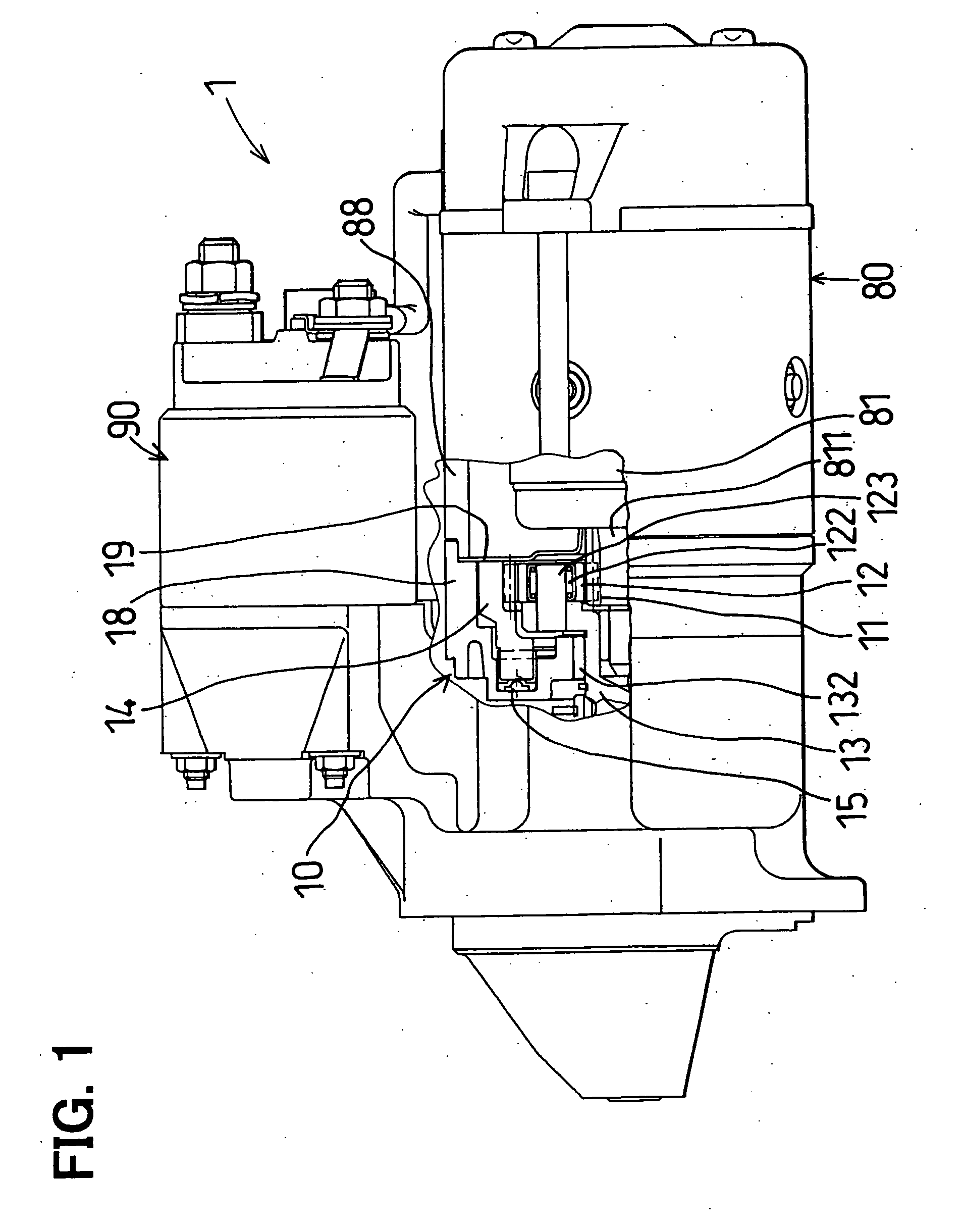
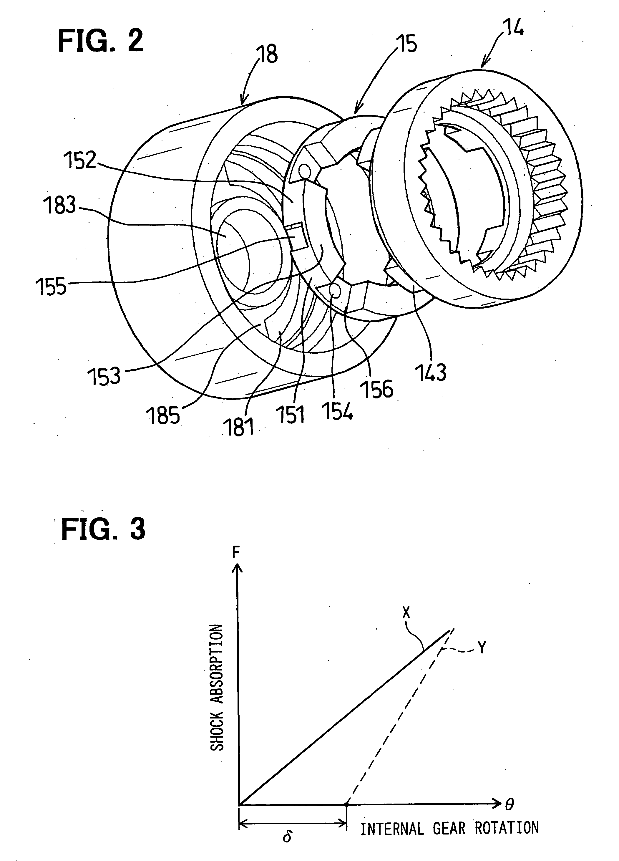
[0040] the present invention will be described hereinafter with reference to FIGS. 1 through 3.
[0041]FIG. 1 shows a gear-type starter (hereinafter, simply referred to as a starter) 1. The starter 1 mainly includes a reduction gear 10, a motor 80 and a magnet switch 90. Although not illustrated in details, an output of the motor 80 is transmitted to an output shaft that is formed with a helical spline on its outer peripheral face via the reduction gear 10.
[0042] An overrunning clutch (one way clutch) and a pinion gear are arranged on the helical spline. (See, FIG. 7) In starting, the overrunning clutch and the pinion gear are pushed in an axially forward direction (to a left side of FIG. 1) by lever operation of the magnet switch 90. Further, the pinion gear is temporarily brought in mesh with a ring gear attached to a crankshaft of the engine to thereby crank the engine. When the engine has been started, the pinion gear of the starter 1 is idly rotated by the overrunning clutch to ...
second embodiment
[0058] Next, the second embodiment will be described with reference to FIG. 4.
[0059] In the second embodiment, a shock absorbing member 25 has a shape different from the shape of the shock absorbing member 15 of the first embodiment. Shock load applied to the internal gear 14 is absorbed by four independent shock absorbing members 25 each having the same shape.
[0060] Each of the shock absorbing member 25 includes a first elastic block portion 251, a second elastic block portion 252 and a bridging portion 253 for bridging the first elastic portion 251 and the second elastic portion 252. An elastic projection 254 is formed on the bridging portion 253 to elastically contact with an axially front end face of the internal gear 14. The shock absorbing member 25 is formed by integral molding of rubber.
[0061] The shock absorbing member 25 is fixed to the gear housing 18 such that a fixed recessed portion 255 formed between the first elastic block portion 251 and the second elastic block p...
third embodiment
[0072] In the third embodiment, the central portion 351c of the first elastic block portion 351 is narrower than the end portions 351a, 351b. Thus, the first elastic block portion 351 is contractable in the circumferential direction. Further, the clearance is formed between the first elastic block portion 351 and the walls of the guide groove 181. Therefore, the first elastic block portion 351 can be stably deformed by an amount of the clearance.
[0073] Further, the end portions 351a, 351b of the first elastic block portion 351, which are elastically in contact with the end face of the locking projection 143, are conversely thickened and therefore, the first elastic block portion 351 can firmly receive reaction force or shock load applied to the internal gear 14. It is preferable that the circumferential end face of the end portion 351a and the circumferential end face of the locking projection 143 which are in contact with each other, have the same size.
PUM
 Abstract
Description
Claims
Application Information
 - R&D
- Intellectual Property
- Life Sciences
- Materials
- Tech Scout
- Unparalleled Data Quality
- Higher Quality Content
- 60% Fewer Hallucinations
Browse by: Latest US Patents, China's latest patents, Technical Efficacy Thesaurus, Application Domain, Technology Topic, Popular Technical Reports.
© 2025 PatSnap. All rights reserved.Legal|Privacy policy|Modern Slavery Act Transparency Statement|Sitemap|About US| Contact US: help@patsnap.com


