Antireflection structure and optical material comprising the same

a technology of anti-reflection structure and optical material, which is applied in the direction of mirrors, instruments, coatings, etc., can solve the problems of disadvantageous application of inability to form predetermined convexes and concaves on the surface of optical material and mass production, and inability to apply the above coating method to optical members disadvantageously, etc., to achieve the effect of effective prevention of light reflection, improved light utilization efficiency, and improved visibility

Inactive Publication Date: 2006-03-23
DAI NIPPON PRINTING CO LTD
View PDF6 Cites 15 Cited by
  • Summary
  • Abstract
  • Description
  • Claims
  • Application Information

AI Technical Summary

Benefits of technology

[0061] The optical member comprising the first antireflection structure or second antireflection structure according to the present invention can effectively prevent light reflection. For example, in the case of an optical member for information display such as display devices, the visibility can be improved, and, in the case of a light receiving optical member such as solar battery panels, the efficiency for light utilization can be improved.
[0062] The antireflection structure according to the present invention can easily be produced from a predetermined replication mold. Specifically, a number of optical members having an antireflection structure can be replicated by providing a replication mold capable of forming the above predetermined antireflection structure and shaping the antireflection structure using this replication mold. According to this method, optical members having an antireflection structure of a substantially identical shape can be produced from a single replication mold.
[0063] Thus, as compared with the method in which, for each product, coating or vapor deposition is carried out, or a diffraction grating is prepared, optical members having a predetermined antireflection structure can be produced very stably in an easy and low-cost manner.
[0064] Further, in the present invention, also for optical base materials having a complicated surface shape, a predetermined antireflection structure can easily be formed.

Problems solved by technology

In order to realize necessary antireflection properties, however, it is not easy to form predetermined convexes and concaves on the surface of the optical material and to mass produce optical members having predetermined convexes and concaves in a stable and low-cost manner.
For example, the above coating method disadvantageously cannot be applied to optical members with a surface having a complicated geometrical shape without difficulties.
The vapor deposition method is disadvantageous, for example, in that an expensive reactor should be used.
Further, the diffraction grating preparation method disadvantageously requires a precision optical system for diffraction grating preparation.
In recent years, an increase in size of the optical member has led to a tendency that the provision of an apparatus suitable for the large optical member cannot be said to be advantageous for economic reasons.
Accordingly, it has been difficult to mass produce an antireflection structure having fine concaves and convexes and an optical member comprising the antireflection structure in a stable, easy and cost-effective manner.

Method used


Image

  • Antireflection structure and optical material comprising the same
  • Antireflection structure and optical material comprising the same
  • Antireflection structure and optical material comprising the same

Examples


example a1

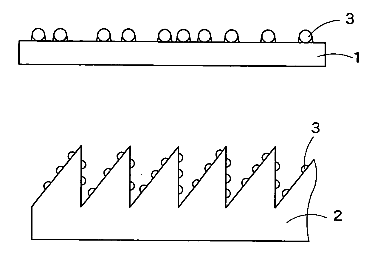
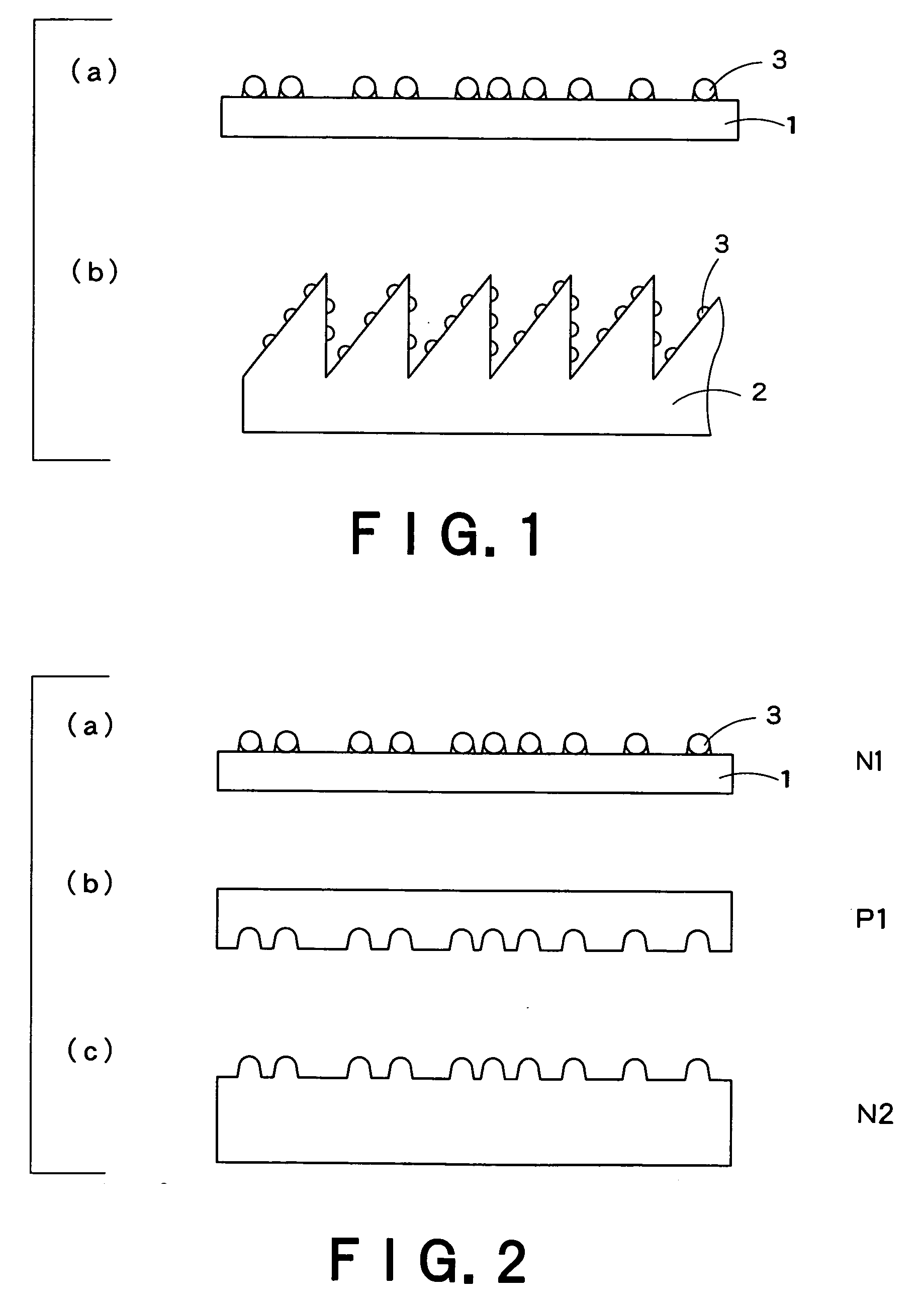
(Preparation of Mold Having Fine Convexes on its Surface (Hereinafter Referred to as “Fine Convex Mold”))

[0185] A 0.4% aqueous polydiallyldimethylammonium salt (product name: PDDA, manufactured by Aldrich) solution containing 0.1 M concentration of sodium chloride and a 0.4% aqueous polystyrenesulfonate (product name: PSS, manufactured by Aldrich) solution containing 0.1 M concentration of sodium chloride were provided.

[0186] A cleaned glass substrate having a size of 5 cm square was immersed in a PDDA solution for 2 min and was thoroughly cleaned, and a PDDA adsorption layer was then formed on the surface of the thoroughly cleaned glass substrate. This substrate was immersed in a PSS solution for 2 min and was then thoroughly washed to form a composite film comprising a PDDA layer and a PSS layer stacked in that order on the surface of the glass substrate (“PDDA / PSS composite film”). This work was repeated 6 cycles, and, finally, a PDDA adsorption layer was provided, whereby a c...

example a2

[0194] (Preparation of Fine Convex Mold)

[0195] A fine convex mold was prepared in the same manner as in Example A1, except that the solid content of the polymer emulsion was regulated to 16%.

[0196] (Evaluation of Fine Convex Mold)

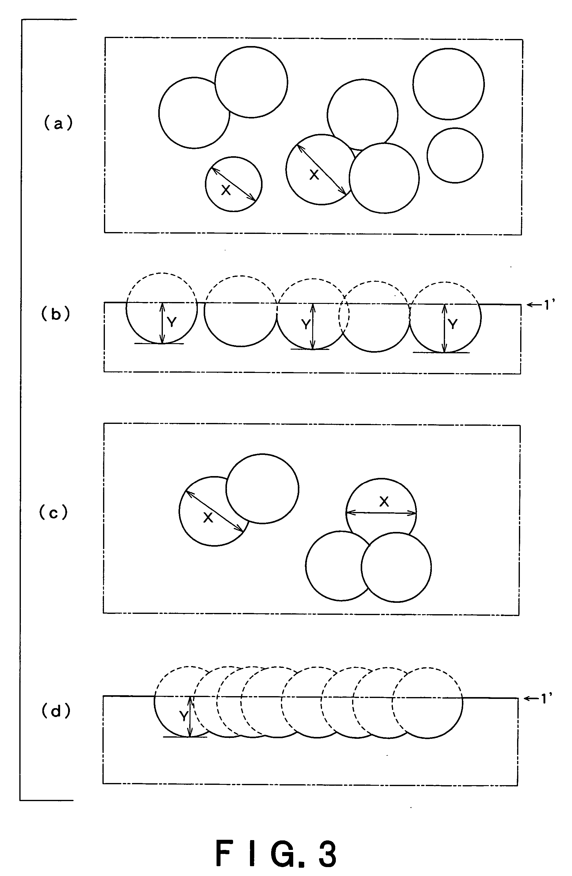
[0197] The measurement of transmittance showed that the fine convex mold had antireflection properties. The mold was observed under a scanning electron microscope. As a result, it was confirmed that the convexes formed of fine particles were randomly distributed at a density of 1689 / 100 μm2, the maximum value, minimum value, and average value of diameters of the convexes were 163 nm, 82 nm, and 140 nm, respectively, and at least 10% of the convexes were provided independently of each other. The maximum value, minimum value, and average value of the height of the convexes were 118 nm, 67 nm, and 99 nm, respectively. Likewise, the cross-section was observed. As a result, it was confirmed that the skirt part of the convexes was in a taper form. The average ...

example a3

[0204] (Preparation of Fine Convex Mold)

[0205] A fine convex mold having an antireflection structure was prepared in the same manner as in Example A1, except that a silica fine particle dispersion liquid (tradename: SPHERICA-SLURRY 120, manufactured by Catalysts and Chemicals Industries Co., Ltd.) having a solid content regulated to 18% was used instead of JSR 0693 having a solid content regulated to 24%.

[0206] (Evaluation of Fine Convex Mold)

[0207] The measurement of transmittance showed that the fine convex mold had antireflection properties. The mold was observed under a scanning electron microscope. As a result, it was confirmed that the basic forms of the convexes formed of fine particles were randomly distributed at a density of 1822 / 100 μm2, the maximum value, minimum value, and average value of diameters of the convexes were 143 nm, 80 nm, and 130 nm, respectively, and at least 10% of the basic forms of the convexes were provided independently of each other. The maximum v...


PUM

PropertyMeasurementUnit
diameteraaaaaaaaaa
diameteraaaaaaaaaa
diameteraaaaaaaaaa

Abstract

An antireflection structure having on its surface an antireflection face having fine concaves or convexes, wherein 10 to 90% of the effective area of the antireflection face is accounted for by the concaves or convexes. The concaves or convexes include basic forms which may be connected to each other. The basic forms have an average length of 30 nm to 200 nm and an average diameter of 80 nm to 400 nm, and the basic forms are substantially irregularly arranged on the antireflection face. The antireflection structure can be used as an optical member to effectively prevent light reflection. For example, in the case of an optical member for information display such as display devices, the visibility can be improved, and, in the case of a light receiving optical member such as solar battery panels, the efficiency for light utilization can be improved.

Description

TECHNICAL FIELD [0001] The present invention relates to an optical material or member, particularly an antireflection structure for preventing or reducing surface reflection of light permeable members, an optical member having this antireflection structure, a display device, and a solar battery panel. Further, the present invention relates to a master, which can mass produce this antireflection structure in an easy and low-cost manner, and a process for producing the same. BACKGROUND ART [0002] In optical members, particularly light permeable members, prevention or suppression of light reflection of the surface has hitherto been carried out. For example, visibility of information display and efficiency of light utilization have been improved by rendering, antireflective, the surface of information display parts of various types of information equipment, for example, display parts such as televisions, computers, portable telephones (cellular phones), and information terminals, solar ...

Claims


Application Information

Patent Timeline
Patent Type & Authority Applications(United States)
IPC IPC(8): G02B5/08
CPCG02B5/003G02B1/11
Inventor HATTORI, HIDESHIKISO, SHOUICHISEKIZUKA, TAKANORIHASEGAWA, TOSHIYUKI
Owner DAI NIPPON PRINTING CO LTD
Why Eureka
Try Eureka