Apparatus and method for transferring DC power and RF signals through a transparent or substantially transparent medium for antenna reception

a technology of dc power and rf signals, applied in the direction of electrical equipment, electromagnetic transmission, transmission, etc., can solve the problems of cumbersome magnetic couplings, difficult to achieve, and inability to provide a versatile trans-glass power interface that can meet all manner of applications

Inactive Publication Date: 2006-03-23
MAXENTRIC TECH
View PDF42 Cites 42 Cited by
  • Summary
  • Abstract
  • Description
  • Claims
  • Application Information

AI Technical Summary

Problems solved by technology

However, these types of approaches do not provide for a versatile trans-glass power interface that provides for all manner of applications, such as mobile phone antennae, satellite or other video reception modalities, intrusion detection / security systems, or vehicular satellite radio systems.
Moreover, the magnetic couplings themselves are cumbersome because the standard DC power utilized in such applications must be converted to AC power in order to affect power transfer in magnetic coupling.
Additionally, the coils utilized in magnetic couplings must be aligned across the glass from each other in order to make the system function properly, something which is both time consuming and difficult to achieve when installing the interface.
Moreover, there is a further problem associated with magnetic couplings because, in certain applications involving exposure to nearby electromagnetic interference (EMI), such as AM / FM broadcast signals from nearby receiving antennas, defrosting elements on car windows, etc., magnetic coupling can interfere with operations of AM / FM radios.
Lastly, any apparatus that accomplishes the transfer of RF signals through a dielectric is highly susceptible to the alignment difficulties of the RF coupling pads, and the prior art systems make no attempt to provide any alignment feedback mechanism to address this issue.

Method used


Image

  • Apparatus and method for transferring DC power and RF signals through a transparent or substantially transparent medium for antenna reception
  • Apparatus and method for transferring DC power and RF signals through a transparent or substantially transparent medium for antenna reception
  • Apparatus and method for transferring DC power and RF signals through a transparent or substantially transparent medium for antenna reception

Examples


Embodiment Construction

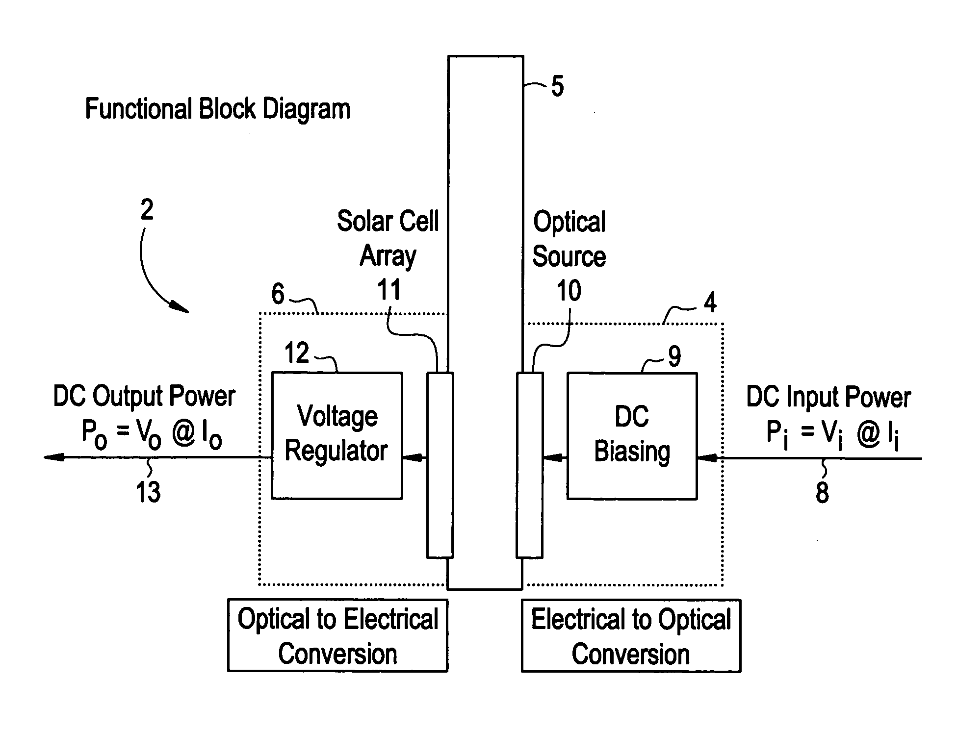
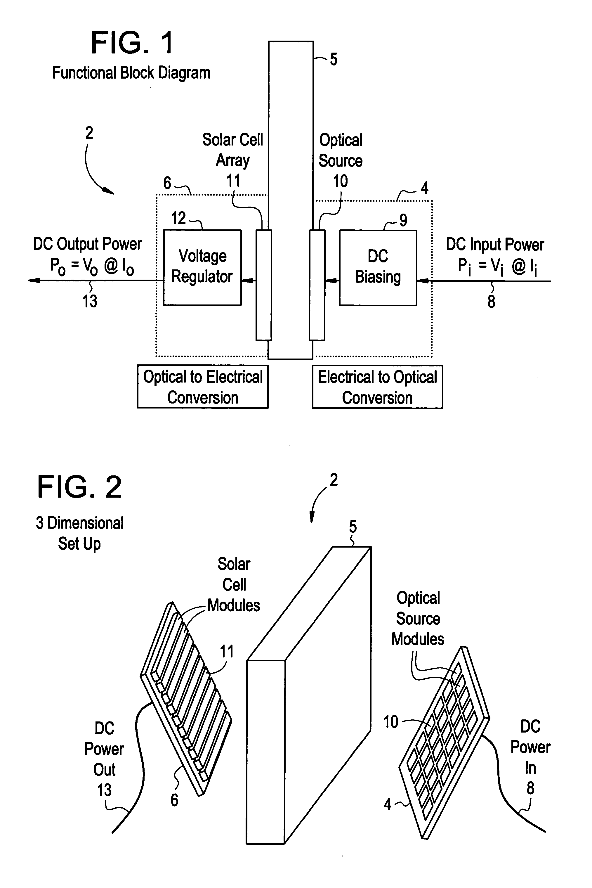
[0016]FIGS. 1 and 2 depict respectively, a functional block diagram, and 3-D offset exploded view of the power transfer part of the inventive interface. With ongoing reference to FIGS. 1 and 2, the inventive interface circuit 2 connects across a substantially transparent medium 5 (e.g., a dielectric such as glass), a first transmission line 8 delivering DC power from a first electronic circuit (not depicted) on a first side of the substantially transparent medium 5, and a second transmission line 13 that is connected to a second electronic circuit (not depicted) on a second side of the substantially transparent medium 5. In one embodiment, the interface 2 comprises an electrical to optical conversion module 4 at the first side for converting an electrical input received along the transmission line 8 from the first electronic circuit to an optical output. The electrical to optical conversion module 4 preferably includes a DC biasing unit 9 for inputting the DC input power into the op...


PUM


Abstract

This invention relates generally to an specific embodiment of an interface for transmitting electrical power through a transparent or substantially transparent medium for use in an active antenna assembly used in vehicular satellite based communication, navigation or entertainment systems chosen from the group of applications consisting of SDARS, GPS, or other vehicular satellite services. A DC power and Radio Frequency wave coupling system is provided which employs RF and DC coupling across a transparent or substantially transparent medium. RF coupling is achieved using low cost and low loss RF coupler pairs such as quarterwave patches that are mounted opposite each other on either side of a transparent or substantially transparent medium. The feeds of the patches are aligned so as to be directly opposite each other, and the patches are mounted against the transparent or substantially transparent medium. A DC power transfer system allows DC power to be transferred across the insolated medium and be available for use by other electronic devices such as Low Noise Amplifiers. An alignment mechanism to facilitate the alignment of the power transfer module and RF coupler pairs.

Description

CROSS-REFERENCE TO RELATED APPLICATIONS [0001] This application hereby incorporates in its entirety the application titled “Apparatus and Method for Transmitting Electrical Power Through a Transparent or Substantially Transparent Medium” (Inventor: Kamran Mahbobi), filed simultaneously with this present application on the day of Sep. 22, 2004. BACKGROUND OF THE INVENTION [0002] This invention relates generally to a specific embodiment of power transfer interface for use in an active antenna assembly of vehicular based communication, navigation or entertainment satellite systems chosen from the group of applications comprising of SDARS, GPS, or other vehicular satellite services. The present invention provides for a DC power and Radio Frequency wave coupling system which offers RF and DC coupling across a transparent or substantially transparent medium. RF coupling is achieved in the present invention using low cost and low loss RF coupler pairs such as quarterwave patches that are m...

Claims


Application Information

Patent Timeline
Patent Type & Authority Applications(United States)
IPC IPC(8): H04B10/00
CPCH04B10/807H04B10/801
Inventor MAHBOBI, KAMRAN
Owner MAXENTRIC TECH
Why Eureka
Try Eureka