Oscillator circuit and semiconductor device having oscillator circuit

a technology of oscillator circuit and oscillator circuit, which is applied in the direction of pulse generator, pulse technique, electric pulse generator circuit, etc., can solve the problems of consumption current, > increase, and high frequency output signal generation

Inactive Publication Date: 2006-03-23
SONY CORP
View PDF2 Cites 20 Cited by
  • Summary
  • Abstract
  • Description
  • Claims
  • Application Information

AI Technical Summary

Benefits of technology

[0032] According to the present invention, the signal modulated in a predetermined format is output as the output signal by using the signal modu...

Problems solved by technology

However, the above-described conventional oscillator circuit 101 is difficult to generate a high frequency output signal S106 because the oscillator circuit is structured so that the output signal S106 having the predetermined frequency is generated by alternately operating ...

Method used


Image

  • Oscillator circuit and semiconductor device having oscillator circuit
  • Oscillator circuit and semiconductor device having oscillator circuit
  • Oscillator circuit and semiconductor device having oscillator circuit

Examples


Embodiment Construction

[0042] In a semiconductor device having an oscillator circuit according to the present invention, the oscillator circuit is formed on a semiconductor substrate. The semiconductor device is not limited only to a single oscillator device (oscillator IC) but includes also a device (IC) mixing various electronic circuits and an oscillator circuit for generating clock signals to be used by the electronic circuits.

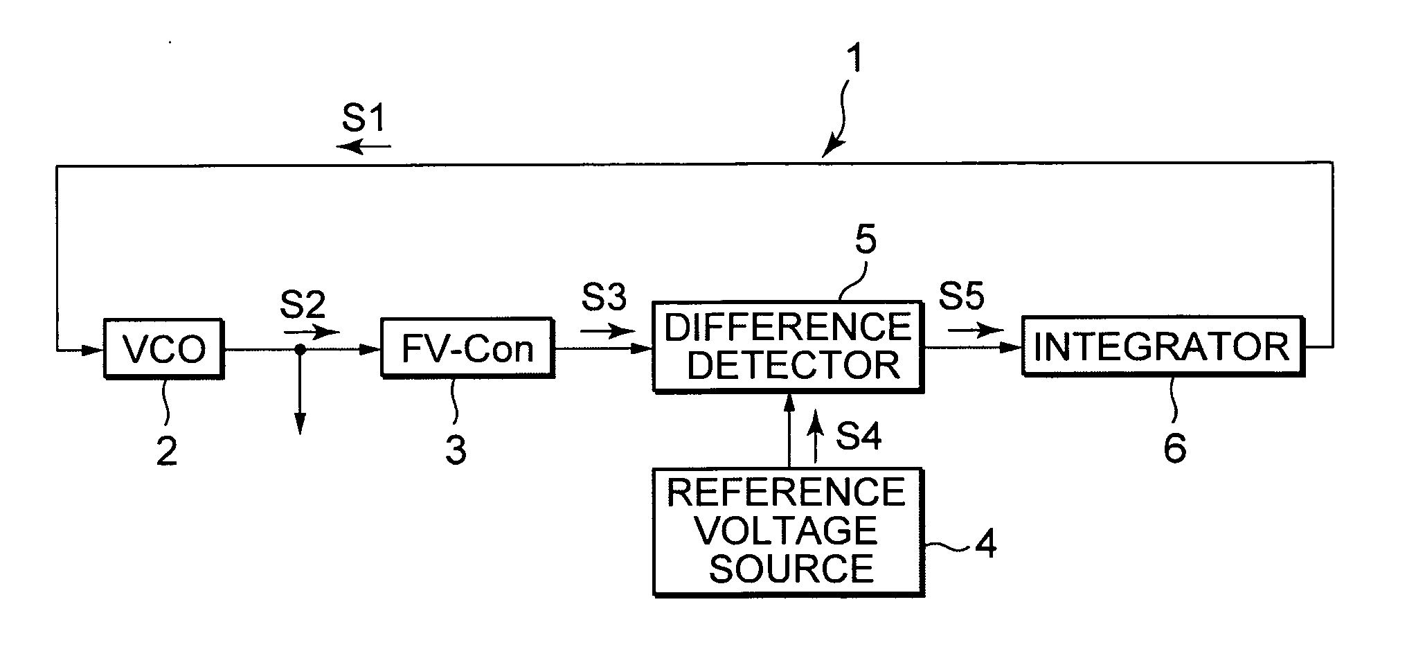
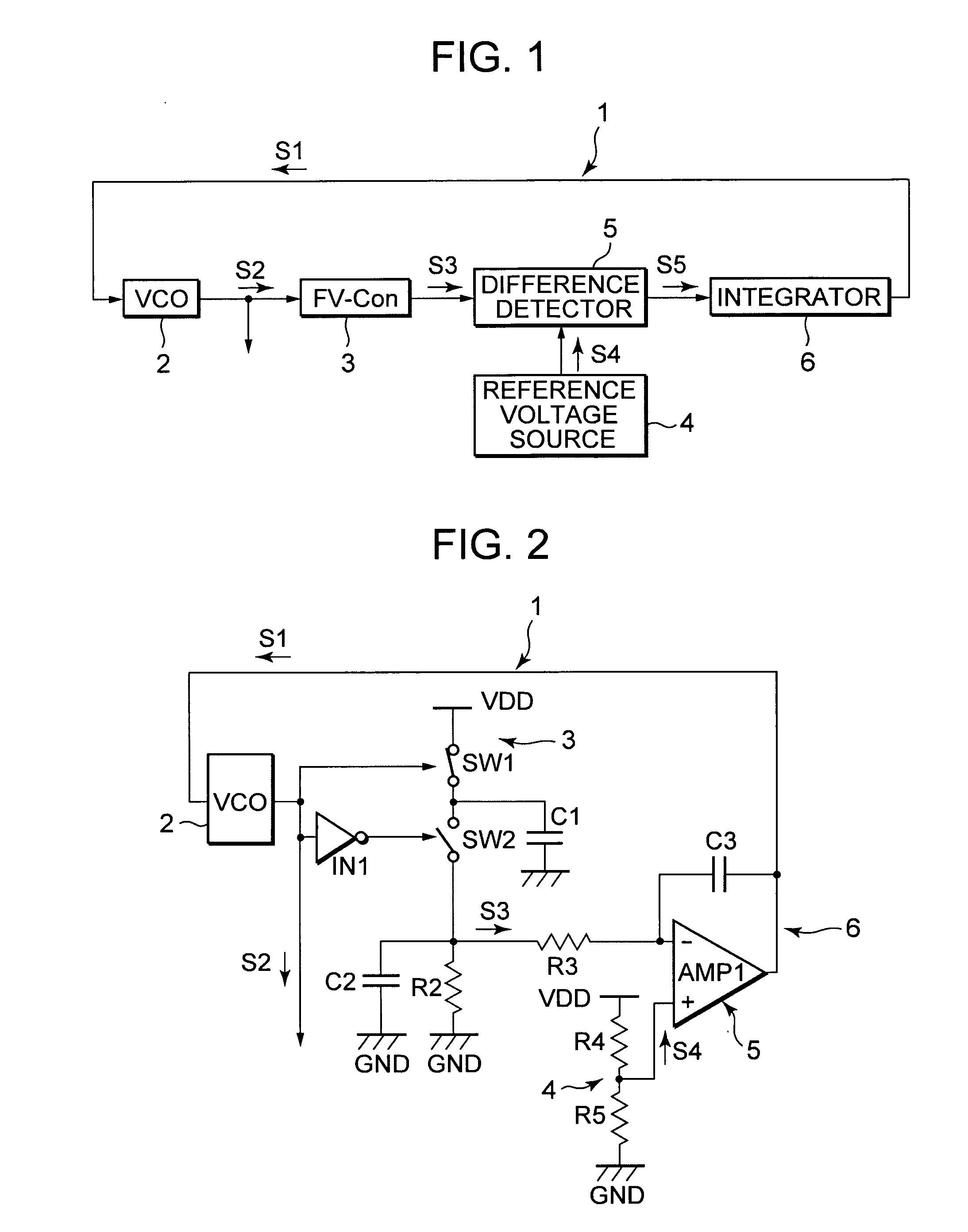
[0043] The oscillator circuit according to the present invention has an oscillator, a frequency / voltage converter, a difference detector and an integrator, which are connected in a closed loop, and generates an output signal oscillating at a predetermined frequency.

[0044] Description will be made on the function of each element constituting the oscillator circuit. The oscillator generates an output signal oscillating at a frequency corresponding to a control signal. The frequency / voltage converter generates a detection signal having a voltage corresponding to a frequency of th...


PUM


Abstract

An oscillator circuit having a closed loop connection, including: an oscillator for generating an output signal oscillating at a frequency corresponding to a control signal; a frequency/voltage converter for generating a detection signal having a voltage corresponding to a frequency of the output signal; a difference detector for generating a difference signal indicating a difference between the detection signal and a reference signal; and an integrator for generating the control signal by integrating the difference signal.

Description

BACKGROUND OF THE INVENTION [0001] 1. Field of the Invention [0002] The present invention relates to an oscillator circuit and a semiconductor device having the oscillator circuit. [0003] 2. Description of Related Art [0004] Electronic circuits built in conventional various electronic apparatuses often use a reference clock signal oscillating at a constant frequency, and an oscillator circuit is used as a circuit for generating the reference clock signal. [0005] A conventional circuit often used as this oscillator circuit has a structure such as shown in FIG. 9. Namely, an oscillator circuit 101 shown in FIG. 9 has: two comparators CMP101 and CMP102 for comparing an input signal S101 with reference signals S102 and S103 having different voltages; an RS type flip-flop FF101 operating by receiving output signals S104 and S105 of the comparators CMP101 and CMP102; a switching transistor TR101 intermittently operating in response to an output signal S106 from the RS type flip-flop FF101...

Claims


Application Information

Patent Timeline
IPC IPC(8): H04B1/40H04B1/06
CPCH03L7/02H03K3/0231
Inventor SHIBUYA, AKIHISATSUKAMOTO, KOJISHIMIZU, YASUHIDETANAKA, TSUYOSHI
Owner SONY CORP
Why Eureka
Try Eureka