Recharging method and apparatus

Active Publication Date: 2006-03-23
UNIVERSITY OF PITTSBURGH
View PDF24 Cites 19 Cited by
  • Summary
  • Abstract
  • Description
  • Claims
  • Application Information

AI Technical Summary

Benefits of technology

[0022] It is another object of the invention to provide such a method and apparatus where

Problems solved by technology

A major problem with inductive charging is that the charging device needs to be in close proximity to the electronic device in order to energized power storage devices in the electronic device.
Also, the size of the dipole antennas for the device do not make it practical for the majority of portable electronic devices (e.g., cellular telephones, portable electronic games, digital camera's and the like).
The problem with the approach as

Method used


Image

  • Recharging method and apparatus
  • Recharging method and apparatus
  • Recharging method and apparatus

Examples


Embodiment Construction

Recharging Apparatus

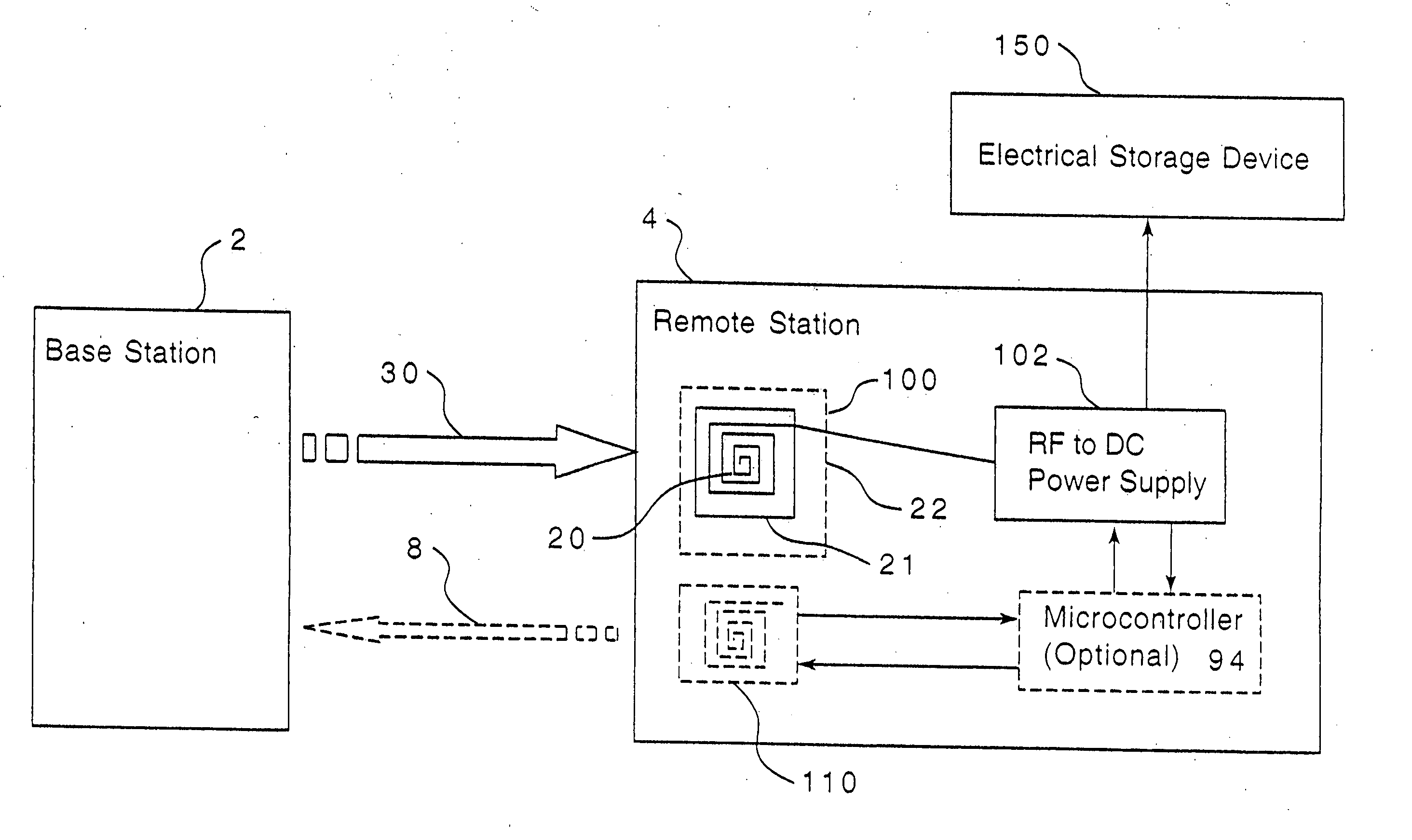
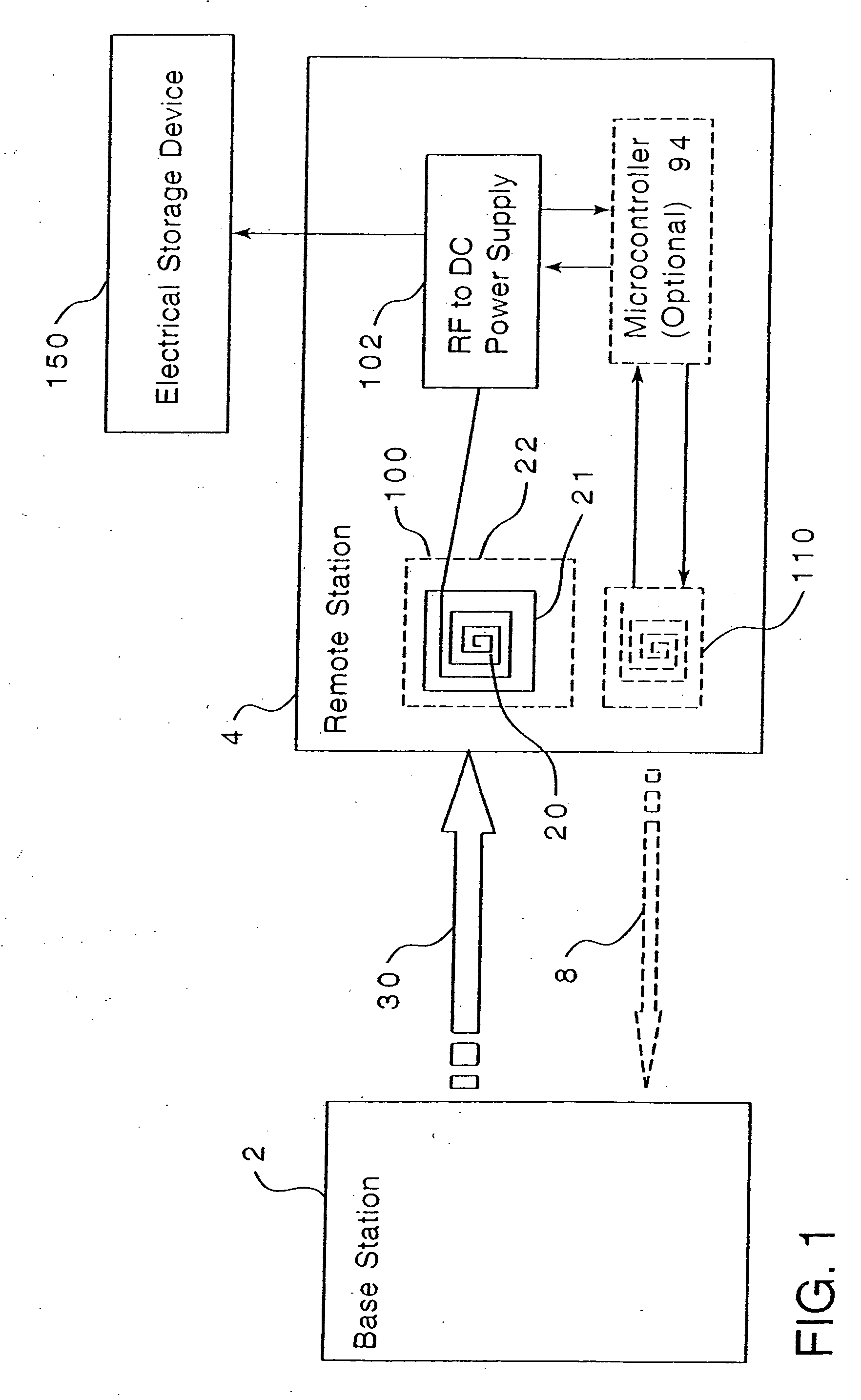
[0029] In one embodiment shown in FIG. 1, an apparatus and associated method for remote energizing of power storage devices comprises a base station 2 and a remote station 4. The base station 2 has a means for transmitting energy 30 in space to the remote station 4. The transmission of energy 30 can be through RF. The remote station 4 has a means for receipt of the transmitted energy 30 and converting the transmitted energy 102 into DC power for energizing the power storage device 150 on the object of interest. The receipt of the transmitted energy 30 on the remote station 4 of this invention is through one or more antennae 100 on the remote station wherein at least one antenna 20 has an effective antenna area 22 greater than its physical area 21. The effective area 22 of the antenna is made greater than its physical area through the use of an LC tank circuit in the antenna. The use of an antenna 100 that has an effective area greater 22 than its physical area ...


PUM


Abstract

The present invention provides apparatus and an associated method for remotely energizing power storage devices. Energization may preferably be effected through the use of RF energy from a base station, ambient energy or ultra-wide band energy. The remote station preferably has at least one antenna having an effective area greater than its physical area. The system may have an antenna and associated circuitry provided on an electronic chip such as a monolithic chip or on a printed circuit with a suitable substrate.

Description

CROSS-REFERENCE TO RELATED APPLICATION [0001] This application is a Continuation-In-Part of U.S. Ser. No. 10 / 459,051 filed Jun. 11, 2003, entitled “RECHARGING METHOD AND APPARATUS” which, this application claims the benefit of U.S. Provisional Application Ser. No. 60 / 411,825, entitled “RECHARGING METHOD” filed Sep. 18, 2002.BACKGROUND OF THE INVENTION [0002] 1. Field of the Invention [0003] This invention relates to a method and associated apparatus for remote energizing of power storage devices and particularly to a method employing small apparatus for remote energizing of power storage devices using RF. The method of this invention preferably employs at least one antenna that has an effective area greater than its physical area to harvest energy. [0004] 2. Description of the Prior Art [0005] Contactless electrical connections are well known in the field of portable electrical devices. For example, portable motorized toothbrushes typically contain a rechargeable battery, which is c...

Claims


Application Information

Patent Timeline
IPC IPC(8): H04B1/16H04B1/38H04B1/00H04M1/00
CPCG06K19/0701H04B1/3883H02J17/00G06K19/0723H02J50/20H02J50/402H02J50/001
Inventor MICKLE, MARLIN H.CAPELLI, CHRISTOPHER C.SWIFT, HAROLDMATS, LEONIDMI, MINHONGGREENE, CHARLES E.
Owner UNIVERSITY OF PITTSBURGH
Why Eureka
Try Eureka