Oil supply device for engine

a technology for oil supply devices and engines, which is applied in the direction of machines/engines, mechanical equipment, auxilaries, etc., can solve the problems of both pumps should be high output pumps, and not being able to supply oil to the destination

Inactive Publication Date: 2006-03-30
AISIN SEIKI KK
View PDF7 Cites 70 Cited by
  • Summary
  • Abstract
  • Description
  • Claims
  • Application Information

AI Technical Summary

Benefits of technology

[0008] In light of the foregoing, the present invention provides an oil supply device for an engine for supplying oil to a lubrication system portion and a cooling system portion of an engine, which includes a first oil suction passage in communication with an oil reservoir which reserves oil, a second oil suction passage in communication with the oil reservoir, a first pump for sucking oil from the first oil suction passage by means of rotation of crankshaft of the engine and for discharging the sucked oil, a second pump arranged in series with the first pump for controlling switching On-Off operation, the second pump configured to be supplied with oil discharged from the first pump and introduced from the second oil suction passage for sucking and discharging oil from at least one of the first p

Problems solved by technology

However, because whether it is necessary to supply oil to the lubrication system portions and the cooling system portions is varied in accordance with temperature of oil and spattered volume of oil (amount of oil mist) and further because there is adequacy of an oil pump used for supplying oil to each portion (e.g., a pump with larger output torque is required when oil viscosity is higher), oil cannot be supplied appropriately to the lubrication system portion and the cooling system portion with known oil supply devices where oil passages are switched on the basis of only the engine rotation speed.
Further, with the construction of the oil supply device according to JPH04 (1992)-132414U, because the

Method used


Image

  • Oil supply device for engine
  • Oil supply device for engine
  • Oil supply device for engine

Examples


first embodiment

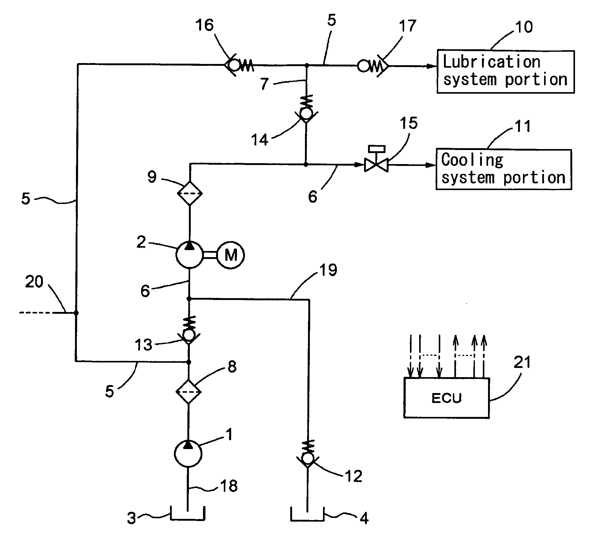
[0018] As shown in FIG. 1, an oil supply device for an engine according to the present invention includes an oil supply circuit which includes a lubrication system portion 10 where oil for lubrication is supplied in the engine and a cooling system portion 11 where the oil for cooling is supplied. For example, the lubrication system portion 10 includes a cam shower for showering oil for lubrication to a cam, and a chain jet for jetting oil for oil to a cam chain, or the like. The cooling system portion 11, for example, includes a piston jet for jetting cooling oil to a piston.

[0019] According to this oil supply circuit, oil is supplied to the lubrication system portion 10 and the cooling system portion 11 from either a first oil reservoir 3 or a second oil reservoir 4. More particularly, the oil supply circuit includes a first pump 1 and a second pump 2 for discharging oil to the lubrication system portion 10 and the cooling system portion 11 by sucking oil from the first oil reservo...

third embodiment

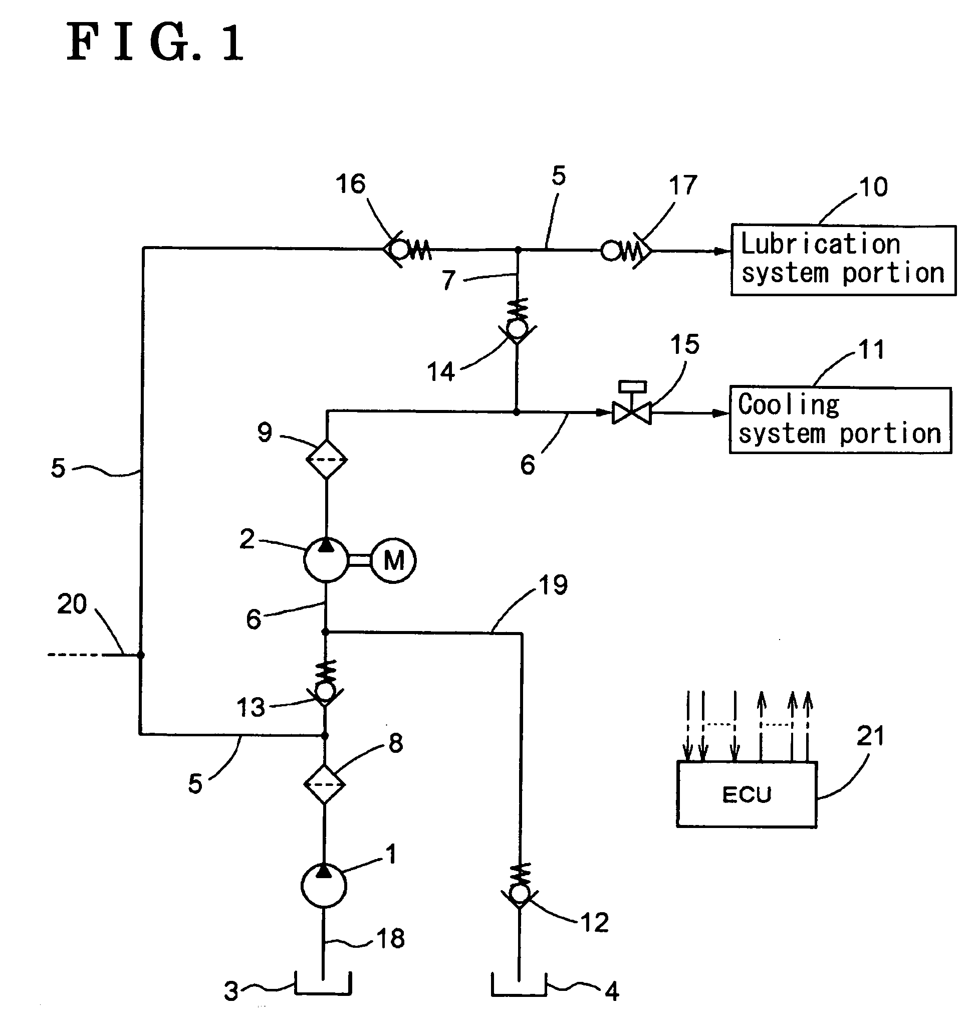
[0040] A third embodiment of the present invention will be explained with reference to FIG. 3. According to the present invention, as shown in FIG. 3, a third valve 27 (i.e., a opening and closing valve) is provided on the first oil passage 5 at the upstream side of the connection point between the first oil passage 5 and the third oil passage 7 instead of the check valve, a third valve 27 (i.e., opening and closing valve) is provided on the first oil passage 5 at the downstream side of the connection point between the first oil passage 5 and the third oil passage 7 instead of the stop valve, and the first valve 14 shown in FIG. 1 is not provided. The ECU 21 commands to open the second valve 26 and the third valve 27 and to close the fourth valve 15 for supplying oil for lubrication only to the lubrication system portion 10 by the first pump 1. The ECU 21 commands to open the third valve 27 and to close the fourth valve 15 and the second valve 26 for supplying oil only to the lubric...

seventh embodiment

[0044] A seventh embodiment of the present invention will be explained with reference to FIG. 7. According to the present invention, the oil pressure actuation portion 33 according to the sixth embodiment is replaced with a shape memory spring 43. An operation of the oil supply device according to the seventh embodiment of the present invention is as follows. First, when the ECU 21 stops the second pump 2, operational oil is supplied from the first pump 1 to the lubrication system portion 10. The ECU 21 operates the second pump 2 with low pressure for discharging oil when engine rotation speed is low and an engine oil temperature is high. As a result, the shape memory spring 43 is expanded by oil temperature of the operational oil, the spool valve biased by a spring 32 is moved to the left in FIG. 7, and operational oil from the second pump 2 is supplied to the lubrication system portion 10. The ECU 21 operates the second pump 2 with high pressure to discharge high-pressured oil whe...


PUM


Abstract

An oil supply device for an engine includes a first oil suction passage, a second oil suction passage, a first pump for sucking and discharging oil from the first oil suction passage, a second pump arranged in series with the first pump, the second pump for sucking and discharging oil from at least one of the first pump and the second oil suction passage, a check valve for blocking oil circulation, a first oil passage, a second oil passage, a third oil passage for establishing communication between the first oil passage and the second oil passage, and a supply volume control device for varying oil supply volume to a lubrication system portion, to a cooling system portion, or to the lubrication system portion and the cooling system portion in accordance with a change in at least one of an engine oil temperature, an engine rotation speed, and an engine load.

Description

CROSS REFERENCE TO RELATED APPLICATIONS [0001] This application is based on and claims priority under 35 U.S.C. §119 with respect to Japanese Patent Application No. 2004-281908 filed on Sep. 28, 2004, the entire content of which is incorporated herein by reference. FIELD OF THE INVENTION [0002] The present invention relates to an oil supply device for an engine. More particularly, the present invention pertains to an oil supply device for an engine, which supplies oil to lubrication system portions and cooling system portions of the engine. BACKGROUND [0003] A known oil supply device for an engine described in JPH04 (1992)-132414U includes a main oil pump (i.e., a first pump) and a motor driven oil pump (i.e., a second pump). According to the known oil supply device, a destination of oil from each pump is changed by appropriately switching oil passages from the both pumps on the basis of engine rotation speed. With the known oil supply device described in JPH04 (1992)-132414U, the f...

Claims


Application Information

Patent Timeline
IPC IPC(8): F01P3/00F01M1/02
CPCF01M1/02F01M1/12F01M2001/123F01M5/002F01M1/16
Inventor IKEGAWA, ATSUTOSHI
Owner AISIN SEIKI KK
Why Eureka
Try Eureka