
Membrane filter cleansing process

a technology of membrane filter and cleaning process, which is applied in the field of membrane filter cleaning process to achieve the effect of reducing the level of liquid and reducing the accumulation of sludg

Inactive Publication Date: 2006-03-30
ZENON TECH PARTNERSHIP
View PDF9 Cites 61 Cited by
  • Summary
  • Abstract
  • Description
  • Claims
  • Application Information

AI Technical Summary

Benefits of technology

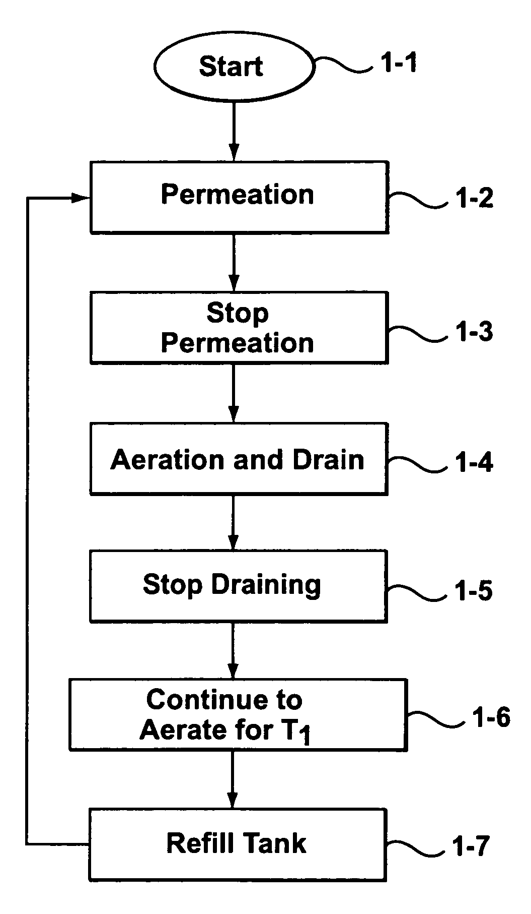
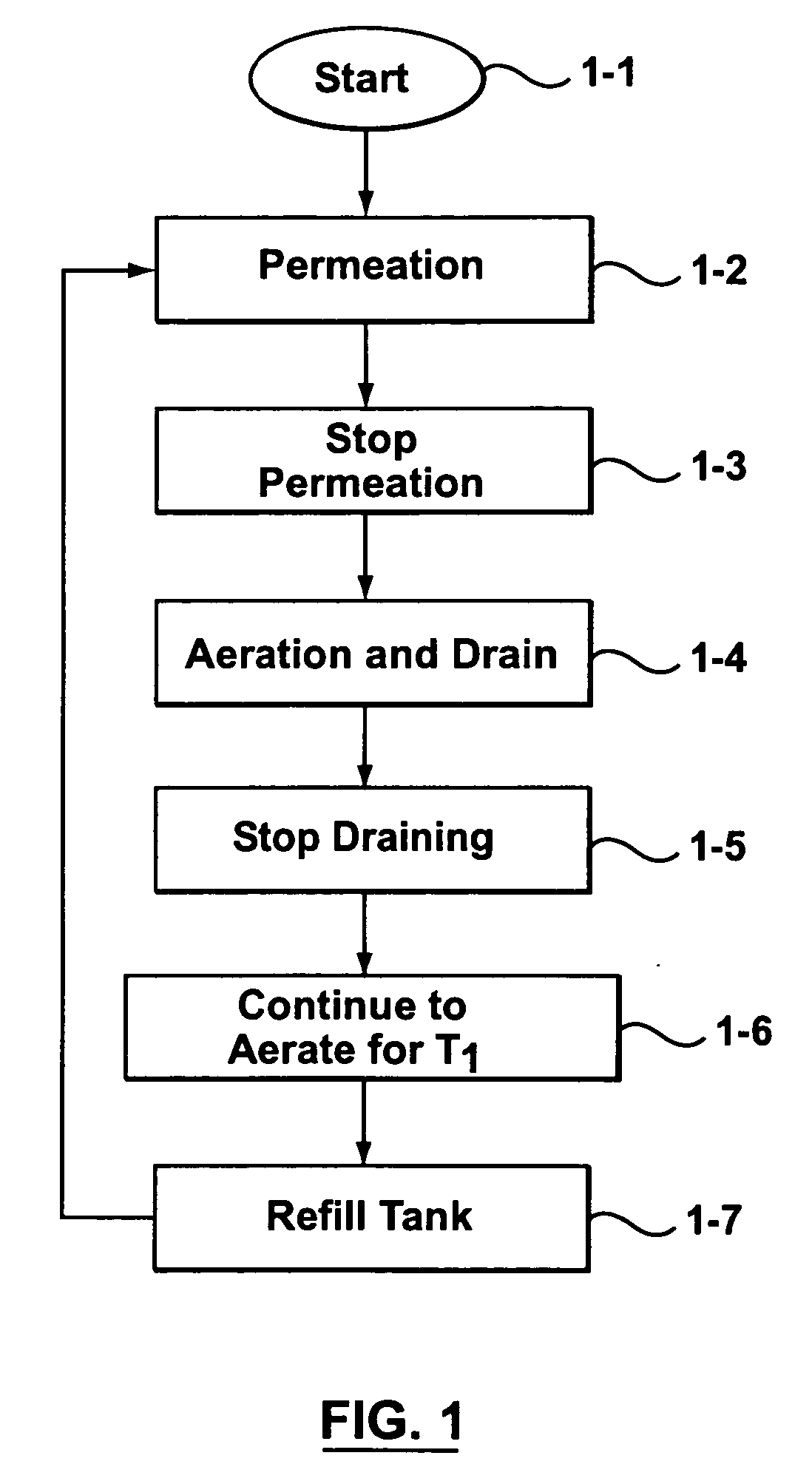
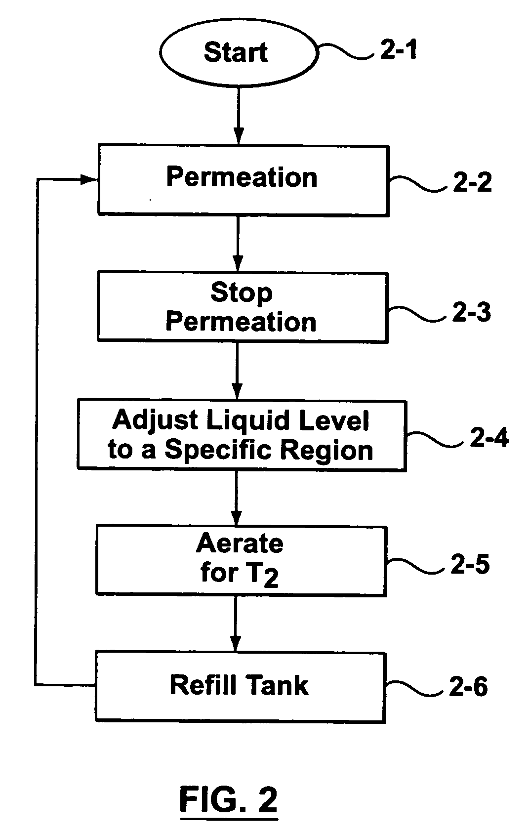
[0008] The inventors have observed that, despite regular backwashing, aeration or chemical cleaning, solids or sludge may still accumulate around the membrane fibers. In particular, sludge may build up in a layer above a lower header of a module of vertical fibers or in other areas of these or other types of modules that are difficult to contact with bubbles under ordinary air scouring. According to aspects of an embodiment of the invention there is provided a process for reducing the accumulation of sludge build-up on membrane fibers immersed in a liquid including: reducing the level of the liquid to or near an area of the membrane fibers having an accumulation of sludge and providing air scouring for a period of time with the liquid at this level in order to dislodge sludge or solids from the membrane fibers. While the invention is not limited to this theory, the inventors believe that energy released by the bubbles bursting at the lowered water surface is highly effective at removing sludge or solids build ups from problem areas in a module. The sludge may be removed from the membrane tank directly thereafter by draining the rest of the tank, or removed later.

Problems solved by technology

In particular, sludge may build up in a layer above a lower header of a module of vertical fibers or in other areas of these or other types of modules that are difficult to contact with bubbles under ordinary air scouring.

Method used


Image

  • Membrane filter cleansing process
  • Membrane filter cleansing process
  • Membrane filter cleansing process

Examples


Embodiment Construction

[0018] As described above immersed hollow-fiber membrane filtration systems sometimes encounter process problems as a result of solids accumulation in and around the hollow-fibers. The solids can accumulate to the point where they begin to dewater and form a mud-like substance known as sludge. In some modules, solids or sludge tends to accumulate primarily in certain locations, for example directly above the lower header in a module of vertical fibers. In some embodiments of the invention there is provided a process for removing solids from the fibers to substantially prevent the accumulation of sludge build-up on the fibers or clean fibers that have been fouled by a substantial sludge build-up. Many of these embodiments involve providing aeration to a membrane tank in which the membrane fibers are immersed.

[0019] Aerating a membrane tank involves pumping air into the tank in a manner that provides bubbles that rise through the liquid in the tank. For example, the air may be pumped...


PUM


Abstract

Immersed hollow-fiber membrane filtration systems sometimes encounter process problems as a result of solids accumulation in and around the hollow fibers. The solids can accumulate to the point where they begin to dewater and form a mud like substance known as sludge. In some embodiments of the invention there is provided a process for substantially preventing the accumulation of sludge build-up on membrane fibers and / or cleansing membrane fibers that have been fouled by a substantial sludge build-up. Many of these embodiments involve aerating a membrane tank in which the membrane fibers are immersed after the water level has been reduced to near the level of solids accumulation. In some embodiments of the invention, the energy released by bursting bubbles at the liquid-air interface is employed to prevent fouling of membrane fibers and / or cleanse fouled membrane fibers.

Description

FIELD OF THE INVENTION [0001] This invention relates to membrane filtering systems, and in particular to a cleansing process for membrane filtering systems. BACKGROUND OF THE INVENTION [0002] Immersed membranes are used for separating a permeate lean in solids from tank water rich in solids. Filtered permeate passes through the walls of the membranes under the influence of a transmembrane pressure differential between a retentate side of the membranes and a permeate side of the membranes. Solids in the tank water are rejected by the membranes and remain on the retentate side of the membranes. Despite the simplicity of this process, the need to clean membrane fibers, to prevent their rapid and sometimes irreversible loss of permeability, is difficult to address. [0003] A batch filtration process may have a repeated cycle of concentration, or permeation, and deconcentration steps. During the concentration step, permeate is withdrawn from a batch of feed water initially having a low co...

Claims


Application Information

Patent Timeline
IPC IPC(8): B01D65/02
CPCB01D63/02B01D65/02B01D65/08C02F1/444B01D2321/04B01D2321/185B01D2315/06
Inventor KENT, FRASER CHARLESROSS, DAVID BRIAN
Owner ZENON TECH PARTNERSHIP
Learn More