Pressure shell, high-pressure tank provided with the pressure shell, manufacturing method of the high-pressure tank and manufacturing apparatus of the high-pressure tank

a technology of pressure shell and manufacturing method, which is applied in the direction of electrical generators, other domestic articles, vessel construction details, etc., can solve the problems of lowering the availability of pressure shells, and achieve the effect of increasing the allowable range of products and enhancing the limit pressure of pressure shells

a technology of pressure shell and manufacturing method, which is applied in the direction of electrical generators, other domestic articles, vessel construction details, etc., can solve the problems of lowering the availability of pressure shells, and achieve the effect of increasing the allowable range of products and enhancing the limit pressure of pressure shells

US20060065664A1Inactive Publication Date: 2006-03-30KYUSHU UNIV

Image

  • Pressure shell, high-pressure tank provided with the pressure shell, manufacturing method of the high-pressure tank and manufacturing apparatus of the high-pressure tank
  • Pressure shell, high-pressure tank provided with the pressure shell, manufacturing method of the high-pressure tank and manufacturing apparatus of the high-pressure tank
  • Pressure shell, high-pressure tank provided with the pressure shell, manufacturing method of the high-pressure tank and manufacturing apparatus of the high-pressure tank

Examples


Embodiment Construction

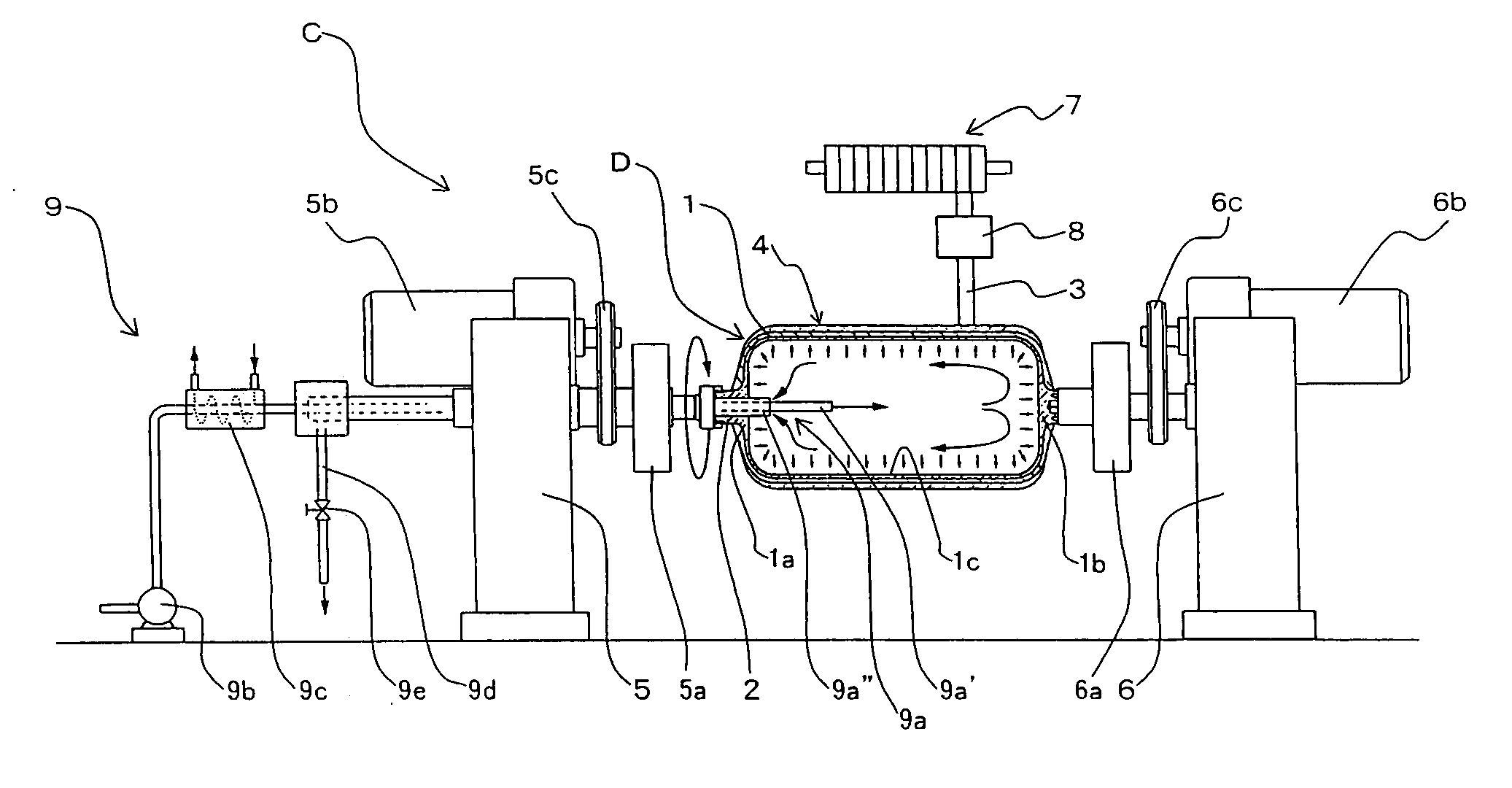
[0031] A pressure shell of the present invention is configured such that a fiber layer is formed by winding reinforcement fibers provided with resin material for hardening around an outer surface of a base body on which the pressure shell is formed, and a large number of fiber layers are laminated to form the laminated structure.

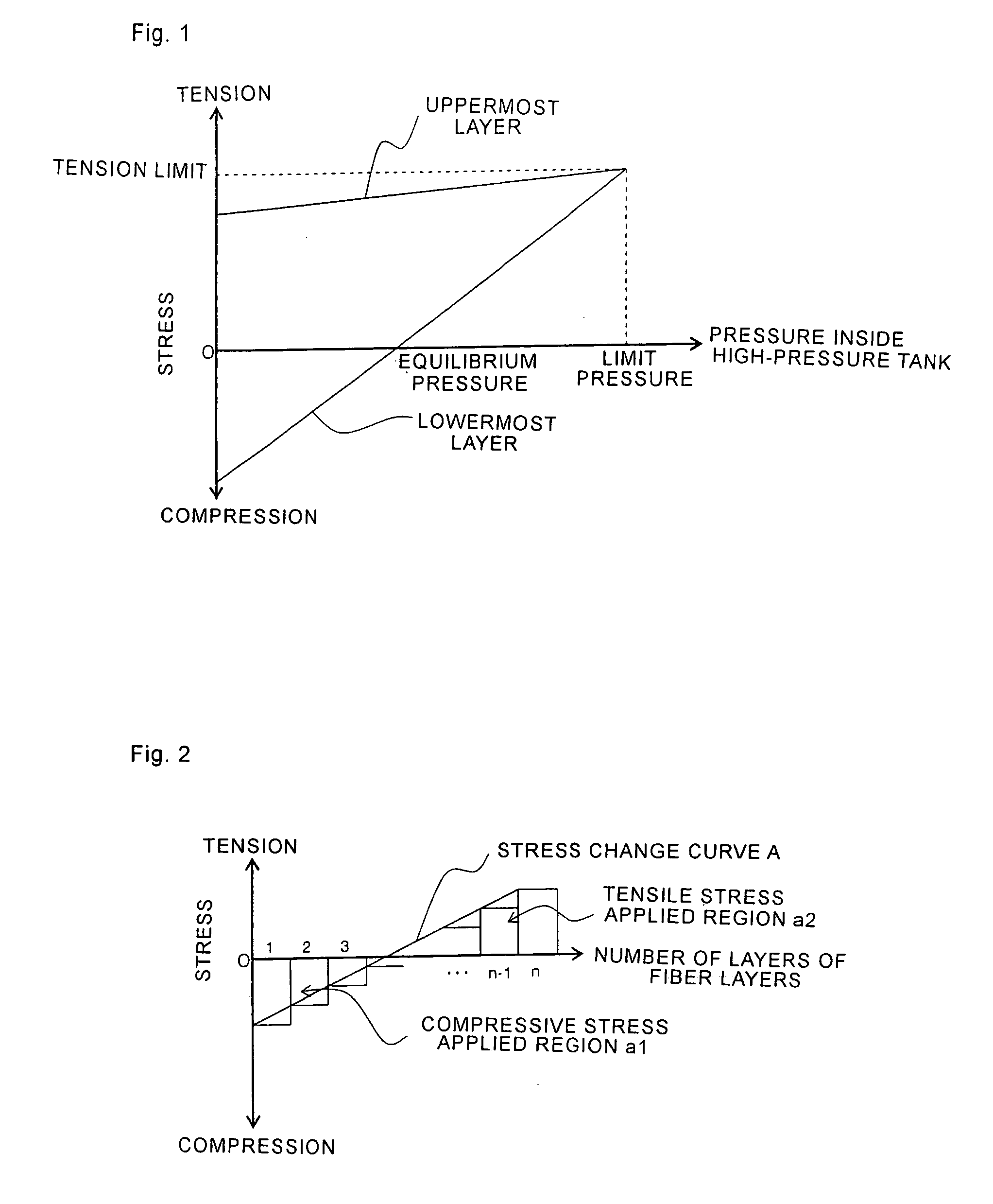
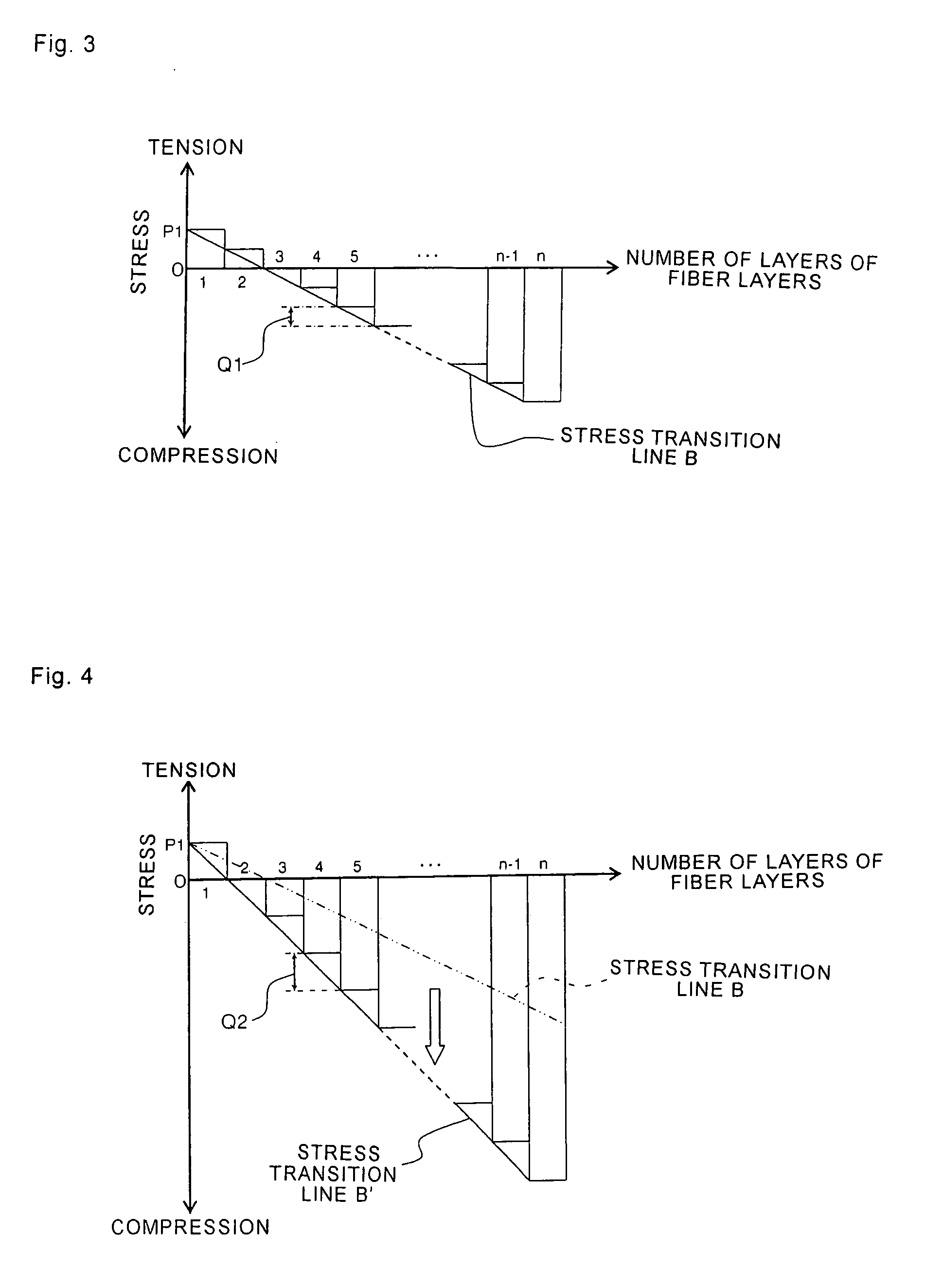
[0032] Particularly, with respect to the pressure shell, in a state that an external force is not applied to the pressure shell, a compressive stress is applied to the lower fiber layer and, at the same time, a tensile stress is applied to an upper fiber layer.

[0033] The compressive stress in the lower fiber layer and the tensile stress in the upper fiber layer are generated by making use of an action that the pressure shell per se is brought into a stress equilibrium state in a state that an external force is not applied to the pressure shell.

[0034] Further, when an expansion pressure is applied to the base body which forms the pressure shell, in the low...


PUM

PropertyMeasurementUnit
Forceaaaaaaaaaa
Pressureaaaaaaaaaa
Pressureaaaaaaaaaa

Abstract

The present invention provides a pressure shell formed by winding reinforcement fibers with resin material for hardening on an outer surface of a hollow tank base body, a high-pressure tank having the pressure shell, a manufacturing method of the high-pressure tank, and an apparatus for manufacturing the high-pressure tank. The pressure shell adopts the laminated structure in which a large number of fiber layers each formed by winding the reinforcement fibers around the tank base body are laminated. In a state the inside of the high-pressure tank is emptied, a compressive stress is applied to a lower fiber layer and a tensile stress is applied to an upper fiber layer. Particularly, in winding the reinforcement fibers around the tank base body, the reinforcement fibers are wound while filling fluid for pressure regulation in the tank base body, regulating a pressure applied to the fluid for pressure regulation, and adjusting a tension applied to the reinforcement fibers.

Description

TECHNICAL FIELD [0001] The present invention relates to a pressure shell which is formed on an outer peripheral surface of a tank which accommodates gas or liquid therein so as to enhance the pressure tightness of the tank, a high-pressure tank provided with the pressure shell, a manufacturing method of the high-pressure tank and a manufacturing apparatus of the high-pressure tank. BACKGROUND OF THE INVENTION [0002] Conventionally, to supply hydrogen used as fuel of a fuel-cell-powered vehicle or to store liquefied oxygen under a severe use condition such as a cosmic space, a high-pressure tank which enhances the pressure tightness is used. [0003] Particularly, Japanese Patent Laid-Open 2002-188794 describes the high-pressure tank in which a tank base body is constituted of a liner made of high-density polyethylene and reinforcement fibers such as carbon fibers to which an adhesive agent such as epoxy resin is applied and which are wound around an outer surface of the liner. [0004] ...

Claims


Application Information

Patent Timeline
30 Mar 2006
Publication
US20060065664A1
IPC
F17C1/06; B29C53/60; B29C70/32; B29C70/56
CPC
B29C53/602; Y02E60/321; B29C70/56; B29L2031/7156; F17C1/06; F17C2201/0109; F17C2201/0119; F17C2201/056
Inventors
OHTA, TOSHIAKI; ONIKURA, HIROMICHI