Bonding tool for ultrasonic bonding and method of ultrasonic bonding

a bonding tool and ultrasonic bonding technology, applied in the direction of manufacturing tools, soldering devices, auxilary welding devices, etc., can solve the problems of inability to achieve stabilized bonding strength and abrasion, so as to prevent the unstable bonding strength of ultrasonic bonds, the effect of preventing the change of pressure welding parts and ensuring the stability of ultrasonic bonds

Inactive Publication Date: 2006-03-30
FUJITSU LTD
View PDF5 Cites 25 Cited by
  • Summary
  • Abstract
  • Description
  • Claims
  • Application Information

AI Technical Summary

Benefits of technology

[0018] The bonding tool for ultrasonic bonding according to the present invention can suppress changes in the form of the pressure welding part of the bonding tool due to use, and therefore can prevent the bonding strength of the ultrasonic bonds from beco

Problems solved by technology

However, when ultrasonic bonding is repeatedly carried out using a bonding tool, abrasion occurs for the pressure welding part of the bonding tool and foreign matter adheres to the pressure welding part, so that the form of the pressure welding part of the bonding tool gradually changes from the initial state.
In this way, when the form of the pressure welding part of the bonding tool 10

Method used


Image

  • Bonding tool for ultrasonic bonding and method of ultrasonic bonding
  • Bonding tool for ultrasonic bonding and method of ultrasonic bonding
  • Bonding tool for ultrasonic bonding and method of ultrasonic bonding

Examples


first embodiment

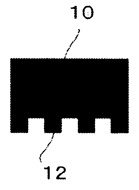
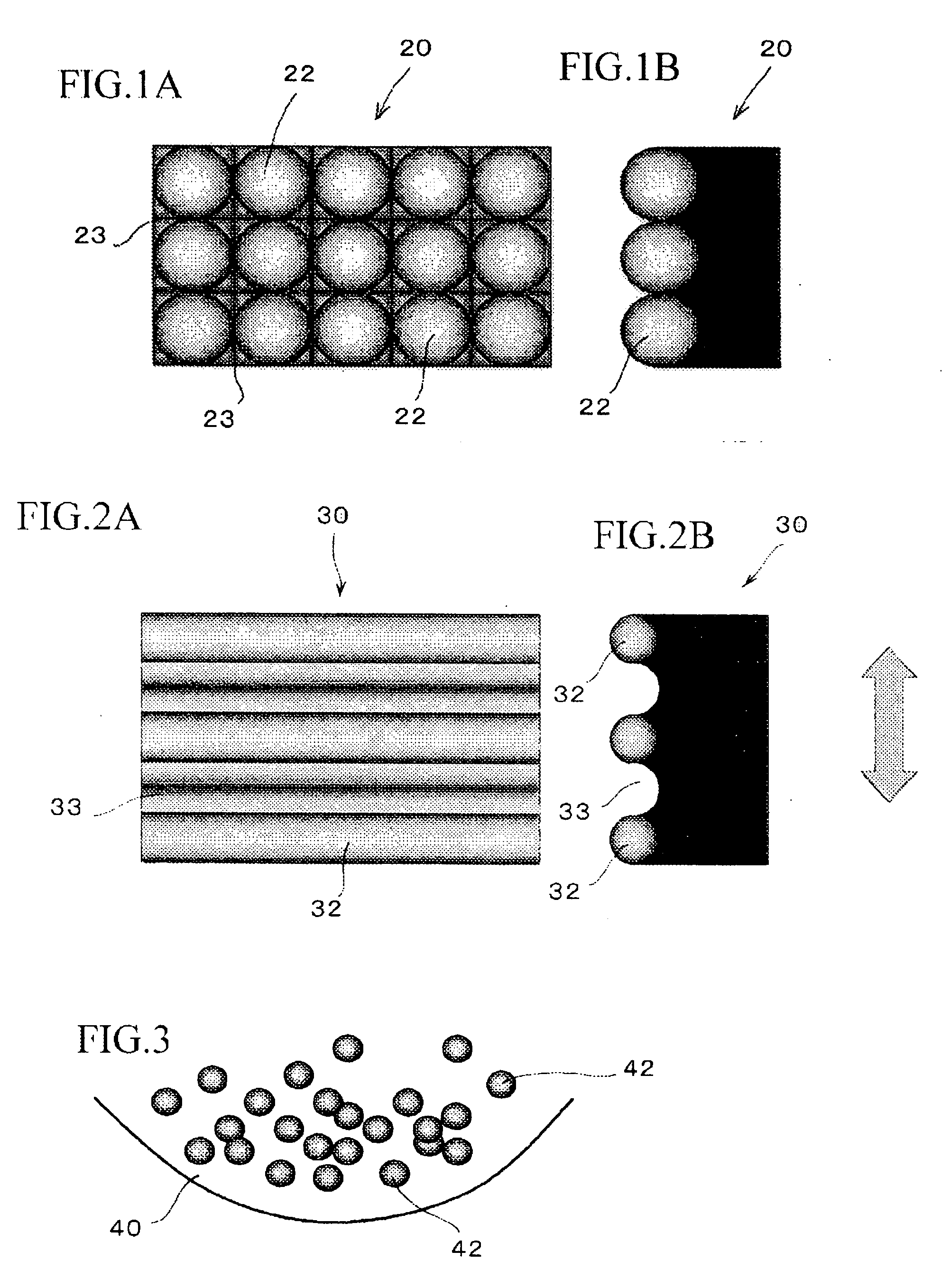
[0029]FIGS. 1A and 1B are respectively an end view and a side view of a bonding tool showing the construction that is a first embodiment of a bonding tool according to the present invention. A bonding tool 20 of the present embodiment is characterized by a plurality of protrusions 22 whose outer surfaces are spherical being formed in a grid arrangement on a pressure welding part of the tool that contacts a bonded part during ultrasonic bonding. As shown in FIG. 1B, the protrusions 22 are formed so as to project outward hemispherically on an end surface of the bonding tool 20.

[0030] The formation of the protrusions 22 whose outer surfaces are spherical on an end surface of the bonding tool 20 may be carried out by forming concave grooves 23 in a grid as shown in FIG. 1A and then sandblasting the end surface of the bonding tool 20.

[0031] Once the concave grooves 23 have been formed in a grid on the end surface of the bonding tool 20 and the end surface on which the concave grooves 2...

second embodiment

[0033]FIGS. 2A and 2B are respectively an end view and a side view of a bonding tool showing the construction that is a second embodiment of a bonding tool. A bonding tool 30 according to the present embodiment is characterized by a plurality of protrusions 32 that are slim and continuously extend in one direction being formed in parallel at predetermined intervals on a pressure welding part of the tool. As shown in FIG. 2B, the protrusions 32 are formed with upper ends that are arc-shaped in cross-section and bottom surfaces of grooves 33, which are formed between adjacent protrusions 32, are also arc-shaped in cross-section, so that a side surface of the pressure welding part of the bonding tool 30 is formed in a wave shape.

[0034] Wire-cut electrical discharge machining may be used to form the protrusions 32 on the pressure welding part of the bonding tool 30 with upper ends that are arc-shaped in cross-section and to form the side surface of the pressure welding part of the tool...


PUM

PropertyMeasurementUnit
Flexibilityaaaaaaaaaa
Abrasion resistanceaaaaaaaaaa

Abstract

Changes in the form of a pressure welding part of a bonding tool for ultrasonic bonding due to abrasion of the pressure welding part and/or accumulation of foreign matter, such as plating material, on the pressure welding part during use of the bonding tool are prevented, so that the bonding tool can carry out ultrasonic bonding stably. A plurality of protrusions with curved outer surfaces are formed on the pressure welding part that contacts the bonded part during ultrasonic bonding. The protrusions can be formed with spherical outer surfaces by forming concave grooves in a grid in an end surface of the bonding tool and then sandblasting the end surface of the bonding tool.

Description

BACKGROUND OF THE INVENTION [0001] 1. Field of the Invention [0002] The present invention relates to a bonding tool for ultrasonic bonding and a method of ultrasonic bonding, and in more detail to a bonding tool for ultrasonic bonding and a method of ultrasonic bonding that are used during assembly and the like of a carriage assembly that composes a magnetic disk apparatus. [0003] 2. Related Art [0004] Ultrasonic bonding is widely used for bonding operations such as the flip-chip bonding of semiconductor chips and the bonding of inner leads of TAB tapes and electrodes. During ultrasonic bonding, it is important to reliably transmit ultrasonic vibration to the parts to be bonded using a bonding tool so that bonding can be carried out stably and reliably. To do so, research is being conducted into carrying out bonding with projections and / or roughened surface parts having been formed on the pressure welding part of an end surface of the bonding tool, which contacts the bonded object a...

Claims


Application Information

Patent Timeline
IPC IPC(8): B23K1/06
CPCB23K20/10H01L2924/01033B23K2201/42H01L24/75H01L24/81H01L2224/16H01L2224/75H01L2224/81205H01L2224/81801H01L2924/01029H01L2924/01078H01L2924/01079H01L2924/01082H01L2924/01005H01L2924/01006B23K20/106B23K2101/42H01L2924/00011H01L2924/00014H01L2224/0401
Inventor KOBAE, KENJIKUBOTA, TAKASHI
Owner FUJITSU LTD
Why Eureka
Try Eureka