
Method for producing thrusts with "Mach" effects manipulated by alternating electromagnetic fields

a technology of electromagnetic field and electromagnetic field, applied in the field of propellantless thrust production, can solve the problem that the force cannot be communicated by methods

Inactive Publication Date: 2006-03-30
WOODWARD JAMES F +2
View PDF10 Cites 17 Cited by
  • Summary
  • Abstract
  • Description
  • Claims
  • Application Information

AI Technical Summary

Benefits of technology

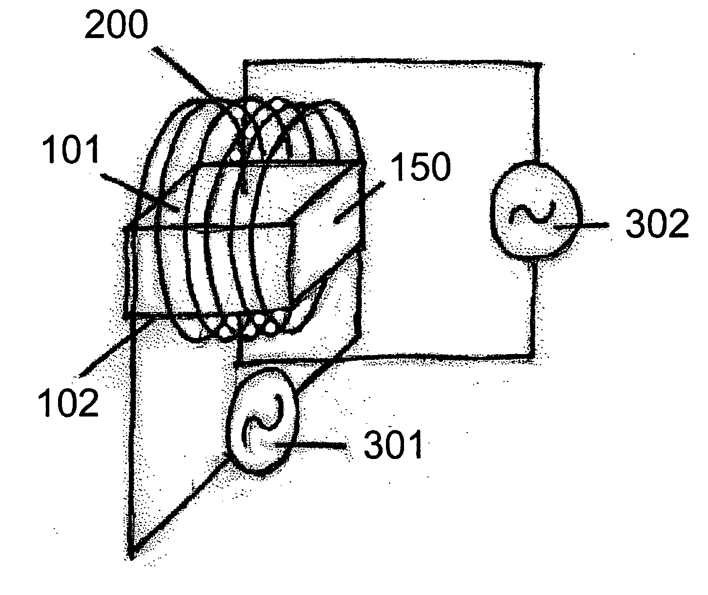
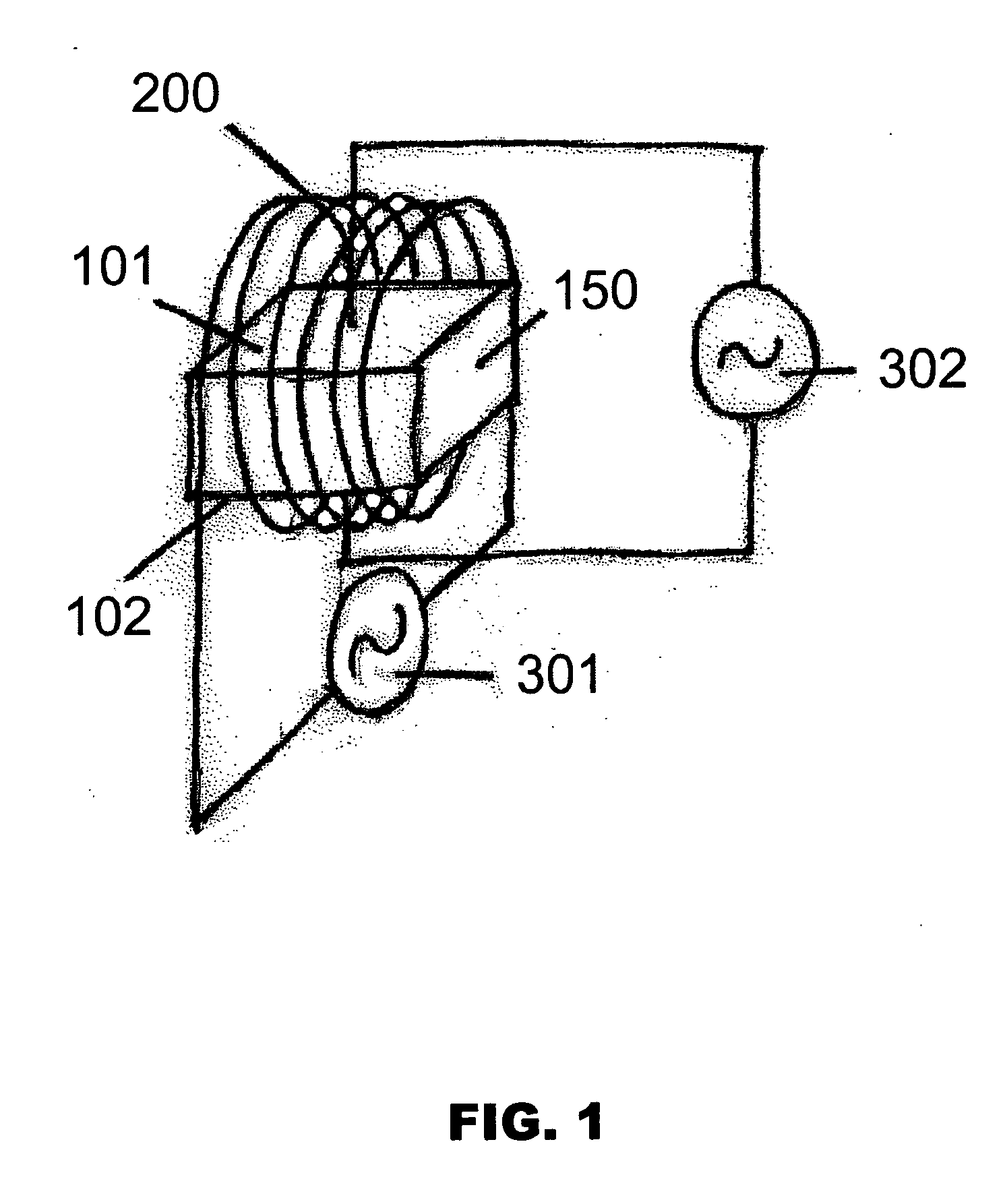
[0008] From the discussion above, it is clear that in order to effect the largest possible stationary force in a system where a mass fluctuation that propagates at light speed through capacitor core material is induced, the second force that acts on the core material, causing the excursion whereby a stationary force is extracted from the system, must also propagate through the core material at light speed. Such forces cannot be communicated by methods that induce sound waves in the material to extract the desired stationary force. But they can be produced by the application of suitable electromagnetic fields, which, like the simple electric fields created by periodically charging the plates of capacitors to produce mass fluctuations, propagate at light speed in the material. A schematic arrangement of a capacitor (wherein mass fluctuations are induced by an alternating applied voltage) and an inductor (that produces an alternating magnetic flux that threads the core of the capacitor which act on the displacement current in the capacitor core) configured to produce the stationary force described in this method is displayed in FIG. 1. Since it consists of a capacitor threaded by a high flux magnetic field, we call it a “flux capacitor”.

Problems solved by technology

Such forces cannot be communicated by methods that induce sound waves in the material to extract the desired stationary force.

Method used


Image

  • Method for producing thrusts with "Mach" effects manipulated by alternating electromagnetic fields
  • Method for producing thrusts with "Mach" effects manipulated by alternating electromagnetic fields
  • Method for producing thrusts with "Mach" effects manipulated by alternating electromagnetic fields

Examples


Embodiment Construction

[0026] The method of this patent, in its full generality, extends beyond systems shown in schematic form in FIG. 1 where mass fluctuations are driven by the application of an electric field to the core material in a capacitor which is then acted upon by a magnetic field generated by a suitably disposed inductor, both fields propagating at lightspeed through the core material of the capacitor and arranged with suitable locked relative phase. For example, instead of using a magnetic field to extract a stationary thrust from the system, a second phase locked double frequency electric field could be used. However, here we explore the details of the flux capacitor system of FIG. 1 to bring out practical concerns involved in the implementation of the method.

[0027] The chief design considerations in the construction of devices of the FIG. 1 type that implement the method are determined by the physical scaling behaviors of the Mach effect and the action of the magnetic flux generated by th...


PUM


Abstract

A method for producing thrusts in devices where a “Mach” effect mass fluctuation is driven by applying a high voltage, high frequency electrical signal to capacitive circuit elements made with high dielectric constant core material and at the same time applying a current signal of the same frequency to inductive circuit elements arranged so that the magnetic fields produced thereby thread the capacitors perpendicular to the electric fields between their plates. With appropriate relative phase established between the electric and magnetic fields in the dielectric material between the plates of the capacitor, the Lorentz force acting on the lattice ions in the dielectric yields a net force. That net force is a consequence of the fact that in each cycle when the Lorentz force acts in one direction the effective masses of the ions are different from their effective masses in the parts of each cycle where lattice forces act to restore the initial configuration. Operated at sufficiently high frequencies and powers, such devices can produce useful levels of thrust.

Description

BACKGROUND OF THE INVENTION [0001] 1. Field of the Invention [0002] The present invention relates generally to propulsion and specifically to a method of producing propellant-less thrust using mass fluctuation. [0003] 2. Background Art [0004] As explained in U.S. Pat. Nos. 5,280,864; 6,098,924; and 6,347,766, and other publications authored by the inventors, when the proper mass of an object changes as a result of the action of an external accelerating force, relativistic gravity that encompasses “Mach's principle” leads to the expectation that the proper mass of the object will change during the interval of the application of the external force. (Mach's principle is the assertion that the inertial reaction forces experienced by agents accelerating massive objects arise from the gravitational action of chiefly distant matter on the objects. This is the case in general relativity theory for certain cosmological models and other relativistic theories of gravity.) The mass fluctuation ...

Claims


Application Information

Patent Timeline
Patent Type & Authority Applications(United States)
IPC IPC(8): B64G1/40
CPCF03H99/00B64G1/409B64G1/417
Inventor WOODWARD, JAMES F.MARCH, PAULMAHOOD, THOMAS L.
Owner WOODWARD JAMES F
Learn More