

Elastomer actuator and a method of making an actuator
a technology of actuators and elastomers, which is applied in the direction of piezoelectric/electrostrictive/magnetostrictive devices, electrostatic motors, piezoelectric/electrostriction/magnetostriction machines, etc., can solve the problems of reducing the performance, reducing the distance between the electrodes, and compressing or tensioning the elastomeric material thereby deformed
- Summary
- Abstract
- Description
- Claims
- Application Information
AI Technical Summary
Benefits of technology
Problems solved by technology
Method used
Image

Examples
Embodiment Construction
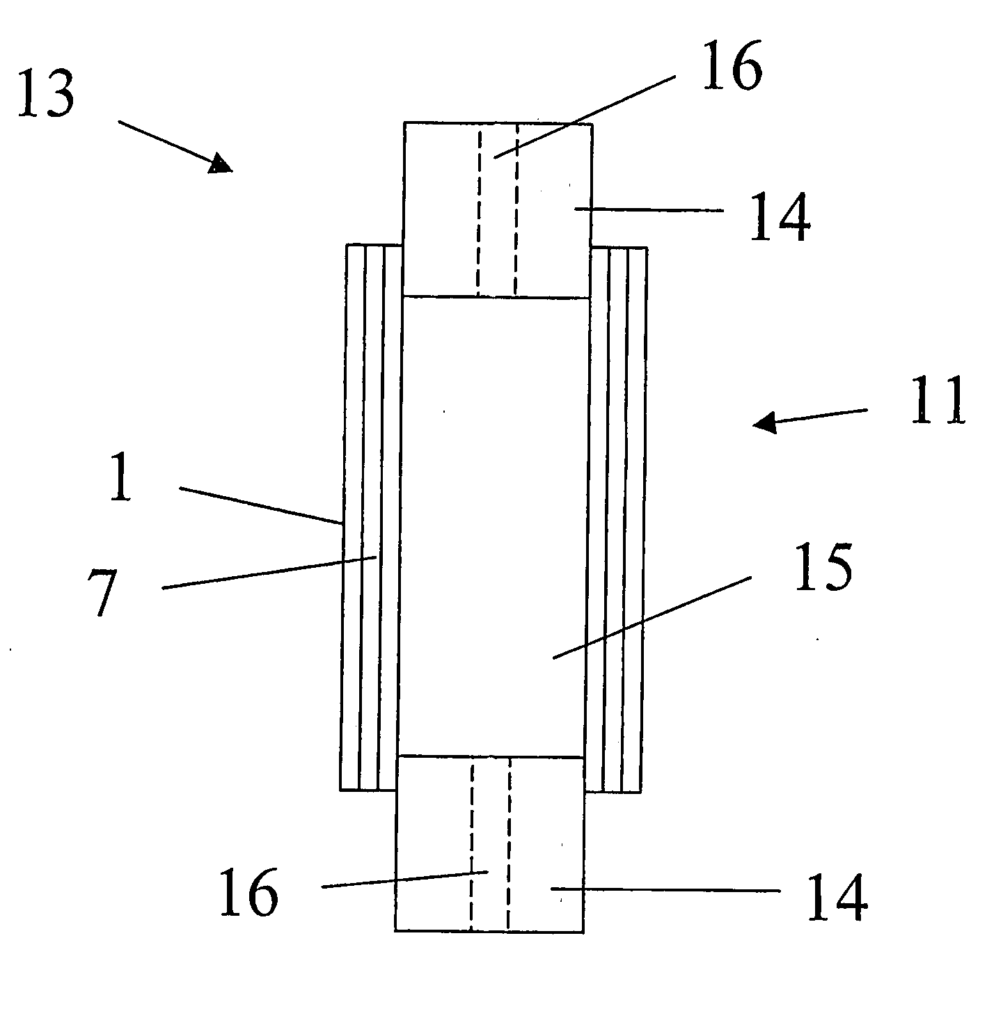
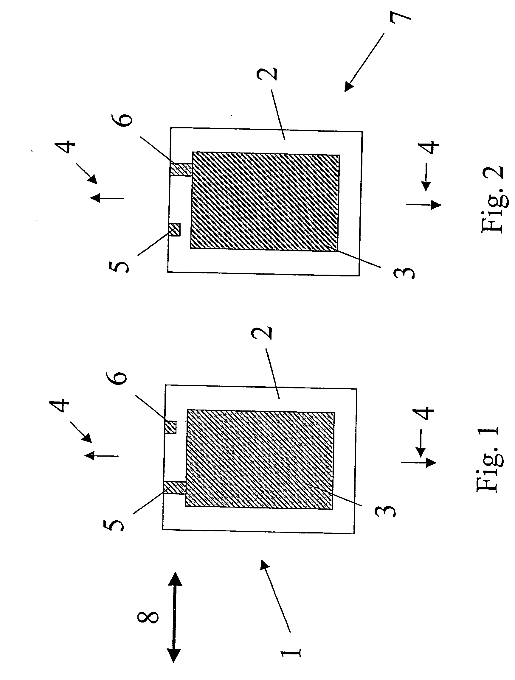
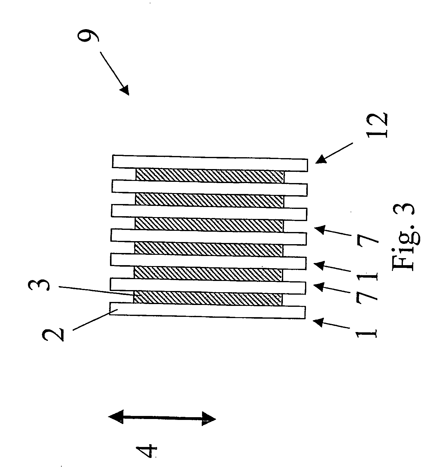
[0005] In accordance with the present invention, provision is made for an actuator made from an elastomer film and which facilitates an improved performance. Accordingly, the present invention in a first aspect provides an actuator comprising a tubular portion extending in a longitudinal direction, the tubular portion comprising a body of an elastomeric material arranged between two electrodes, wherein any line of symmetry extending between two opposite points on a periphery in a cross-section perpendicular to the longitudinal direction has a length which is different from any other such line of symmetry.
[0006] In other words there may be provided an actuator with a cross-section having no lines of symmetry, one single line of symmetry or a plurality of lines of symmetry all being of different lengths.
[0007] As an example, the shape may be non-circular or non-quadrangular. As an example, the actuator may, in that cross-sectional view, expose two axis of symmetry having different l...
PUM
| Property | Measurement | Unit |
|---|---|---|
| size | aaaaa | aaaaa |
| thickness | aaaaa | aaaaa |
| thickness | aaaaa | aaaaa |
Abstract
Description
Claims
Application Information