Low drift superconducting high field magnet system

a high-field magnet and low-drift technology, applied in the direction of superconducting magnets/coils, using reradiation, magnetic materials, etc., can solve the problem of uncontrollable charging of one circuit, and achieve the effect of minimizing the stray field and facilitating the handling of the mechanical stress on the coil system

a high-field magnet and low-drift technology, applied in the direction of superconducting magnets/coils, using reradiation, magnetic materials, etc., can solve the problem of uncontrollable charging of one circuit, and achieve the effect of minimizing the stray field and facilitating the handling of the mechanical stress on the coil system

US20060066429A1Active Publication Date: 2006-03-30BRUKER BIOSPIN

Image

  • Low drift superconducting high field magnet system
  • Low drift superconducting high field magnet system
  • Low drift superconducting high field magnet system

Examples


Embodiment Construction

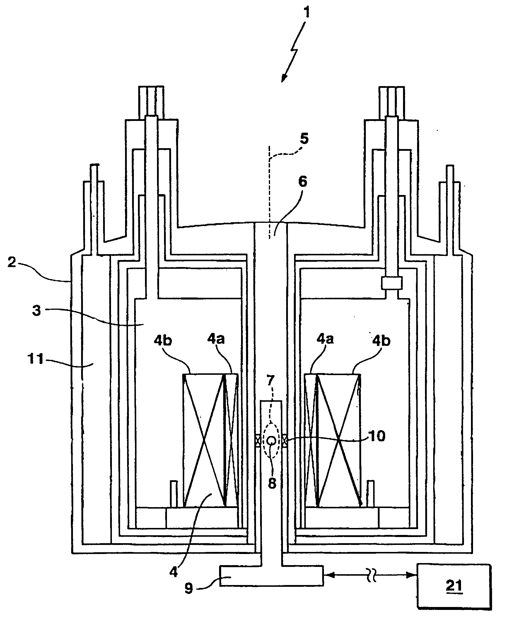
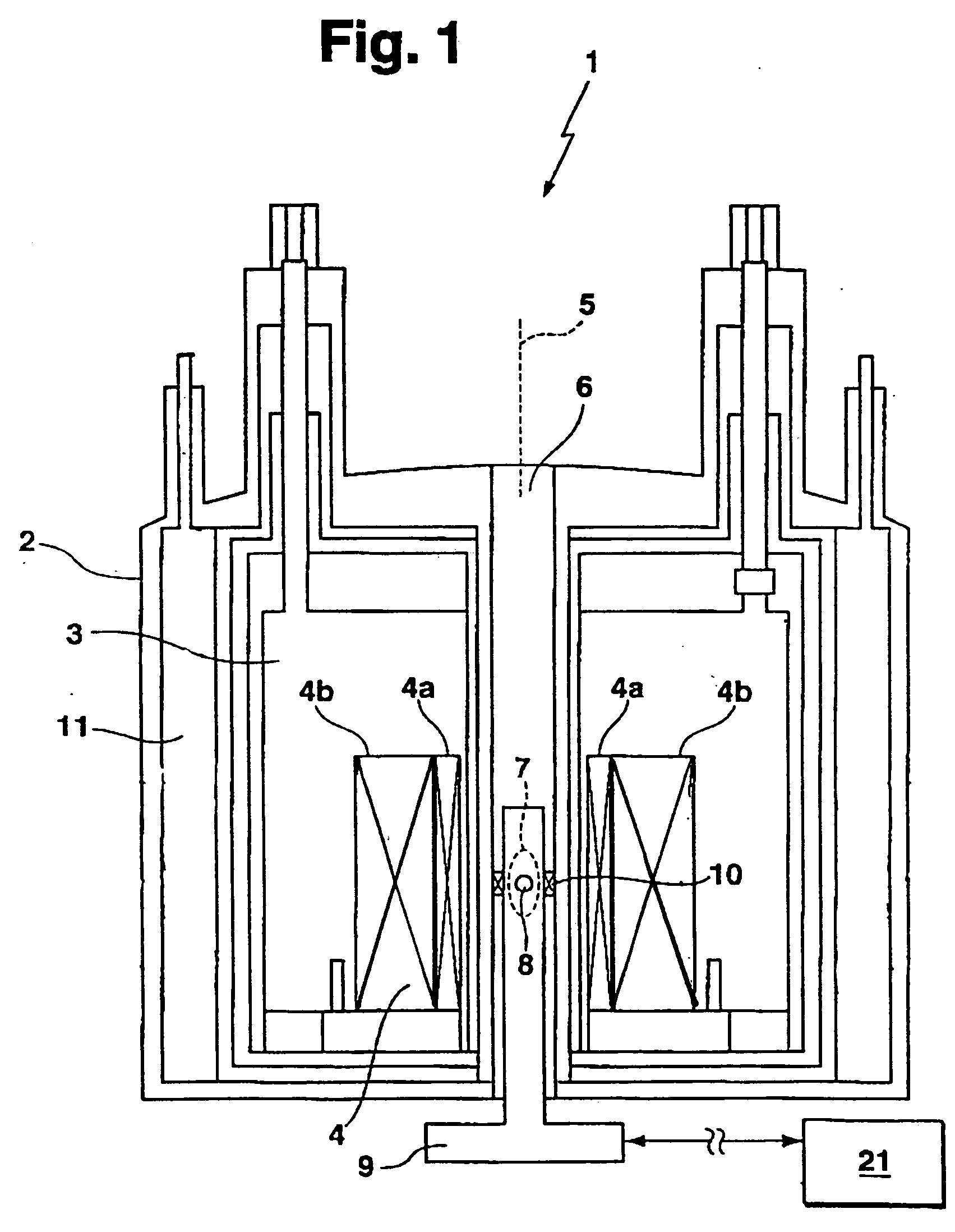
[0036]FIG. 1 schematically shows, in detail, a section through the substantially rotationally symmetrical cryostat of the superconducting magnet system 1, e.g. of a high-resolution NMR apparatus. The magnet coil 4 which is superconductingly short-circuited during operation and consists of two partial regions, i.e. of two partial coils 4a (first partial coil—HTS) and 4b (second partial coil—LTS) is disposed in a helium tank 3 of the cryostat 2. The cryostat 2 has a room temperature bore 6 along its cylinder axis 5 within which, in a measuring region 7 at the center of the magnet coil 4, a sample 8 is disposed which is surrounded by a radio-frequency (RF) transmitter and receiver coil arrangement 9 (probe head).

[0037] A so-called lock coil 10 is also located inside the room temperature bore 6, optionally integrated in the probe head 9, for fine correction of the magnetic field in the measuring region. This lock coil 10 is not or only slightly coupled to the magnet coil 4. The correct...


PUM

PropertyMeasurementUnit
superconductingaaaaaaaaaa
magnetic resonance spectroscopyaaaaaaaaaa
temperatureaaaaaaaaaa

Abstract

The invention concerns a superconducting high-field magnet system (1) for a high-resolution magnetic resonance spectrometer, comprising a magnet coil (4) which is superconductingly short-circuited during operation, and generates a homogeneous temporally stable magnetic field during operation that meets the requirements for taking a high-resolution magnetic resonance spectrum. The magnet coil (4) comprises an LTS partial coil (4b, 4c) and an HTS partial coil (4a, 4d). The LTS partial coil (4b, 4c) can be separately short-circuited in a pure LTS circuit (14b) via an LTS switch (15b), and the HTS partial coil (4a, 4d) can be separately short-circuited in a pure HTS circuit (14) via an HTS switch (15a) and both partial coils (4a, 4d; 4b, 4c) are connected via an LTS-HTS joint (20) and are charged by the same power supply.

Description

[0001] This application claims Paris Convention Priority of DE 10 2004 007 340.6 filed Feb. 16, 2004 the entire disclosure of which is hereby incorporated by reference. BACKGROUND OF THE INVENTION [0002] The invention concerns a superconducting high-field magnet system for a high-resolution magnetic resonance spectrometer, comprising a substantially cylindrical cryostat with an axial room temperature bore for receiving a sample, and a radio-frequency transmitting and detecting system, with a magnet coil which is superconductingly short-circuited during operation and which is disposed at a low temperature in a region within the cryostat to surround the sample in the room temperature bore and to generate a homogeneous, temporally stable magnetic field at the sample location during operation, wherein the magnetic field meets the requirements for obtaining a high-resolution magnetic resonance spectrum. [0003] High-resolution nuclear magnetic resonance (NMR) spectrometers must have magne...

Claims


Application Information

Patent Timeline
30 Mar 2006
Publication
US20060066429A1
IPC
H01F3/00; G01R33/3815; H01F6/00
CPC
H01F6/00; G01R33/3815; H01F6/06
Inventors
KASTEN, ARNE