Method of recording information on optical recording medium, and information recording and reproducing apparatus

a technology of optical recording medium and information recording apparatus, which is applied in the field of recording information on optical recording medium, information recording and reproducing apparatus, can solve the problems of thermal interference between the adjacent recording marks or thermal interference between tracks, slow cooling structure of the light incident side recording layer, and the problem of thermal interference between the recording marks or the cross-erase between tracks, etc., to prevent thermal interference and prevent thermal interference

Inactive Publication Date: 2006-03-30
TDK CORPARATION
View PDF4 Cites 6 Cited by
  • Summary
  • Abstract
  • Description
  • Claims
  • Application Information

AI Technical Summary

Benefits of technology

[0018] As a result of keen examination, the inventor of the present invention found the following. When a recording mark is formed by a write pulse and a cooling pulse, the same number of write pulses and cooling pulses are used if the recording mark length is 4T or more. At the same time, an average value of the cooling pulse widths and a total pulse width of the cooling pulses are set to be within respective given ranges, so that the thermal interference between the adjacent recording marks and the cross-erase between the tracks can be prevented.
[0025] The present invention can prevent thermal interference between the adjacent recording marks and cross-erase between tracks when the recording marks are formed on an optical recording medium. In particular, in a semi-transparent recording layer including a thin metal heat-sink layer, the present invention has an effect of remarkably preventing the thermal interference between the adjacent recording marks and the cross-erase between the tracks.

Problems solved by technology

As a result, the light incident side-recording layer has a slow cooling structure.
Therefore, there arises a problem of thermal interference between the adjacent recording marks or thermal interference between tracks, called cross-erase.
The thermal interference between the recording marks or the cross-erase between the tracks as described above is a problem not only in multi-layered optical recording media but also in single-layered optical recording media.
However, any of the above countermeasures increases the number of power levels of a laser pulse, inducing another problem that the modulation of laser becomes difficult.
According to these strategies, however, a write pulse width tends to increase (become wider) in proportion to a length of a clock cycle because the write pulse width with respect to the clock cycle with which the laser pulse is synchronized is not taken into consideration.
In particular, the recording layer having a slow cooling structure has a problem that the cross-erase becomes noticeable.

Method used


Image

  • Method of recording information on optical recording medium, and information recording and reproducing apparatus
  • Method of recording information on optical recording medium, and information recording and reproducing apparatus
  • Method of recording information on optical recording medium, and information recording and reproducing apparatus

Examples


first exemplary embodiment

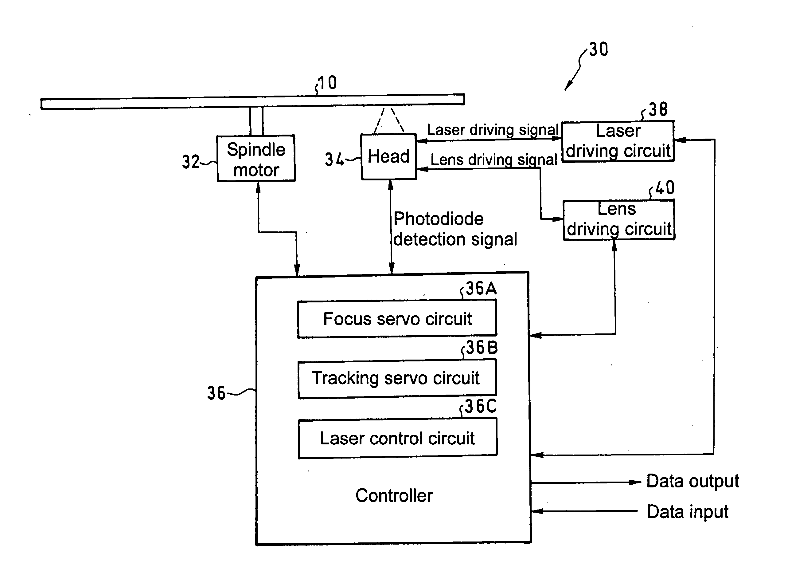
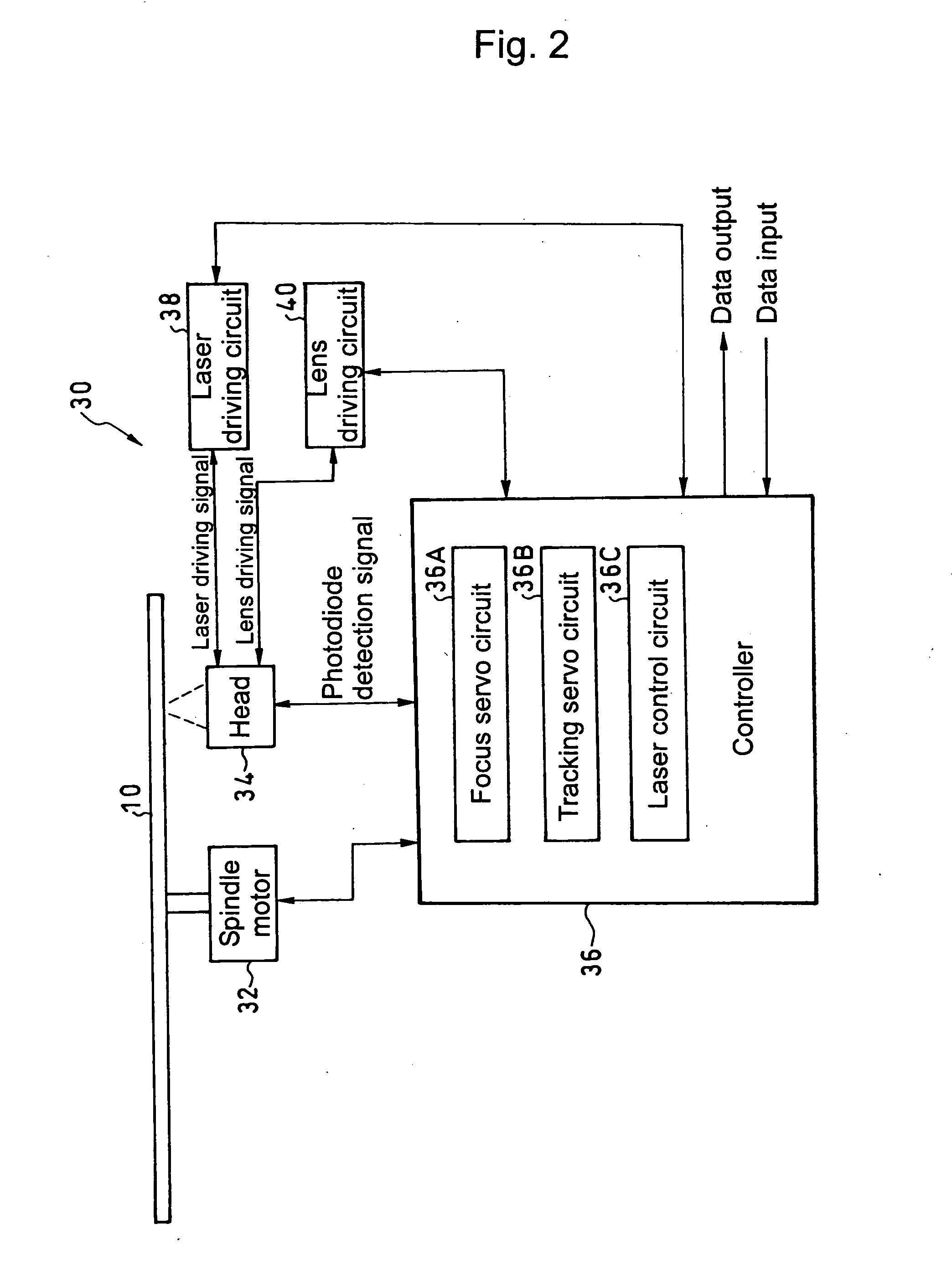
[0031] Hereinafter, a first exemplary embodiment of the present invention will be described in detail with reference to FIGS. 1 and 2.

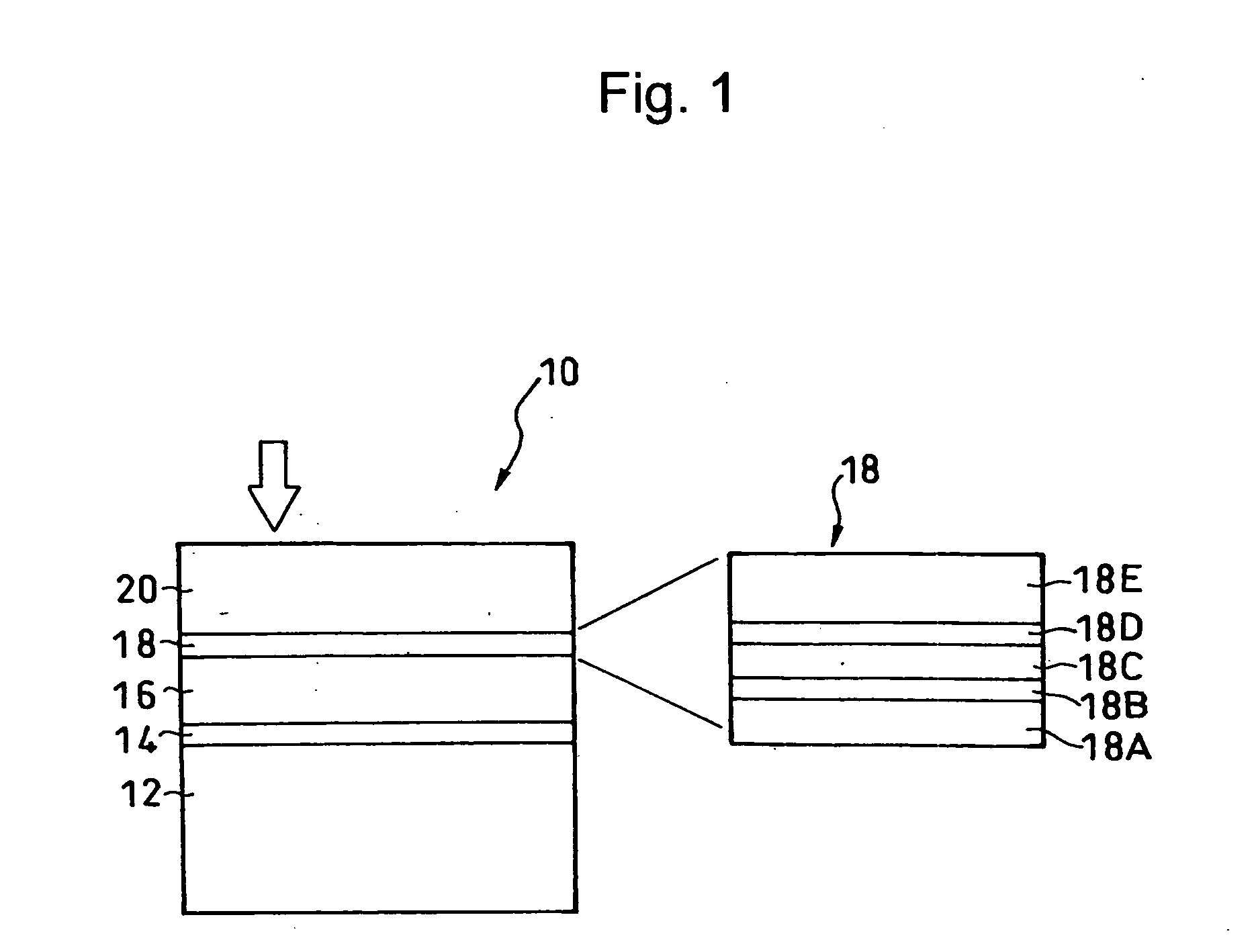
[0032] An optical recording medium 10, on which information is to be recorded by a method according to the first exemplary embodiment, includes: a substrate 12; a first recording layer (an L0 layer) 14; a transparent intermediate layer 16; a second recording layer (hereinafter, simply referred to as a recording layer) 18 (an L1 layer); and a light transmitting layer 20. The above-mentioned layers 14 to 20 are deposited in this order on the substrate 12.

[0033] As is illustrated in FIG. 1 in an enlarged manner, the recording layer 18 includes: an underlayer 18A; a metal heat-sink layer 18B; a second protective layer 18C; a phase-change recording layer 18D; and a first protective layer 18E, deposited in this order from the side of the transparent intermediate layer 16.

[0034] The metal heat-sink layer 18B serves for heat dissipation and an optical inte...

second exemplary embodiment

[0054] A second exemplary embodiment of the present invention will now be described.

[0055] A recording strategy according to the second exemplary embodiment is set as follows in addition to the recording strategy according to the first exemplary embodiment described above. The single write pulse width Tw is set to satisfy: 0.2

[0056] If the single write pulse width Tw is too long, heat is normally accumulated in a track width direction of the optical recording medium when a recording mark is formed, whereby the cross-erase is likely to occur. However, if the single write pulse width Tw is set to satisfy: 0.2

example 1

[0058] In Example 1 of the present invention, the double-layered optical recording medium shown in FIG. 1 was fabricated as follows so as to evaluate recording and reproduction characteristics of the second recording layer.

[0059] The optical recording medium included: the substrate having a thickness of 1.1 mm; the transparent intermediate layer having a thickness of 25 μm; and the light-transmitting layer having a thickness of 75 μm.

[0060] The phase-change recording layer included in the second recording layer was made of an Sb eutectic alloy and had a thickness of 6 nm. The metal heat-sink layer was made of an Ag alloy and had a thickness of 15 nm. The first protective layer, the second protective layer, and the underlayer layer were formed as laminate layers made of dielectric materials, AlN, ZnS.SiO2, and ZrO2, respectively. The thicknesses of these layers were 55 nm, 5 nm, and 20 nm, respectively.

[0061] After the phase-change recording layer was converted to a crystalline st...


PUM

PropertyMeasurementUnit
light transmittanceaaaaaaaaaa
thicknessaaaaaaaaaa

Abstract

An information recording method enables the precise formation of a recording mark on a recording layer having a high light transmittance such as an L1 layer of a double-layered optical recording medium. The information recording method uses the following recording strategy. A laser beam is pulse-modulated so as to create a pulse series including a write pulse of a recording power and a cooling pulse of a base power. Data to be recorded is modulated to have a length of a recording mark along a track of the recording layer. At the same time, the length of the recording mark is made to correspond to an integral multiple nT of T where T is one clock cycle. An nT recording mark corresponding to nT is recorded by using the same number of write pulses and cooling pulses when n is 4 or larger. Moreover, an average width AveTc for a single cooling pulse width Tc is set to satisfy: 1.0<AveTc / T<1.6 and a total pulse width SumTc of the used cooling pulses is set to satisfy: 0.5≦SumTc / nT≦0.8.

Description

BACKGROUND OF THE INVENTION [0001] 1. Field of the Invention [0002] The present invention relates to an optical recording medium including a recording layer having a semi-transparent structure, a method of recording information on the optical recording medium, and an information recording and reproducing apparatus. [0003] 2. Description of the Related Art [0004] There is, for example, a so-called phase-change double-layered optical recording medium including two recording layers, each being formed of a phase-change recording layer, i.e., an L0-layer (a rear-side layer) and an L1-layer (a front-side layer). [0005] In an optical recording medium such as a DVD (Digital Versatile Disc), data to be recorded is modulated to have a length of a recording mark along a track of a recording layer. At the same time, the recording is performed while the length of the recording mark is made to correspond to an integral multiple nT of T where T is one clock cycle. For example, in a CD-RW (compact ...

Claims


Application Information

Patent Timeline
Patent Type & Authority Applications(United States)
IPC IPC(8): G11B7/00
CPCG11B7/0062G11B2007/0013G11B7/24038
Inventor MIZUSHIMA, TETSUROMIURA, HIDEAKIKATO, TATSUYAKAKIUCHI, HIRONORISHINGAI, HIROSHIYOSHINARI, JIRO
Owner TDK CORPARATION
Why Eureka
Try Eureka