
Hydrodynamic bearing device, spindle motor and disc recording and reproducing apparatus

Inactive Publication Date: 2006-03-30
PANASONIC CORP
View PDF5 Cites 1 Cited by
  • Summary
  • Abstract
  • Description
  • Claims
  • Application Information

AI Technical Summary

Benefits of technology

[0028] In the above-described hydrodynamic bearing device according to the present invention, pressure of the lubricant filled between the gap between the shaft and the sleeve, the gap between the flange and the sleeve, and the gap between the flange and the thrust plate maintains the rotational axis stable while one of the shaft and the sleeve is rotating around the other. Particularly, pressure of the lubricant filled in the gaps above and below the flange prevents the shaft from substantially titling from the axial direction of the sleeve and substantially displacing in the axial direction. In this way, the above-described hydrodynamic bearing device according to the present invention rotates the shaft or the sleeve rapidly with a high precision and a stable manner.
[0032] In the above-described hydrodynamic bearing device according to the present invention, a distance between the outer peripheral surface of the flange and the inner surface of the sleeve is kept large across the entirety of the outer peripheral surface. Thus, loss torque can be kept low.
[0033] On the other hand, the above-described secondary flow, i.e., eddy changes its direction smoothly along the inner surface of the sleeve in the vicinity of the inner surface. Therefore, in the eddy, a flow rate is kept high in the range covering the vicinity of the inner surface of the sleeve and the vicinity of upper and lower boundaries of the outer peripheral surface of the flange. As a result, the lubricant is efficiently pumped from the gap near the outer peripheral surface of the flange to the gaps above and below the flange.
[0034] Particularly, when a thrust dynamic pressure generating groove is provided on at least one of a circular surface of the flange, the inner surface of the sleeve which opposes the circular surface, and a surface of the thrust plate, circulation along the thrust dynamic pressure generating groove is rapid. Therefore, a period of time necessary for the pressure of the lubricant to be raised sufficiently in the gaps above and below the flange after the flange or the sleeve started to rotate is short.
[0035] As described above, the hydrodynamic bearing device according to the present invention has low loss torque and a short period of time necessary for the pressure of the lubricant to be raised sufficiently in the gaps above and below the flange after the flange or the sleeve started to rotate.
[0036] Thus, when such a hydrodynamic bearing device is used for a spindle motor, a period of time necessary for the spindle motor to stabilize the rotation after it is started is short. Moreover, when such a spindle motor is mounted on the disc recording and reproducing apparatus, a rotation efficiency of the disc is further improved in the disc recording and reproducing apparatus and startup from the halting state or standby state can be further speeded up. In addition, the durability further improves, realizing further extension of the life.

Problems solved by technology

Furthermore, the reliability on such a rotation has to be maintained high for a long period of time.
Therefore, it is difficult for the oil 42 to move beyond the protrusion 33D.
However, since the oil 42 cannot easily move beyond the protrusion 33D, the pressure gap cannot be eased by circulation of the oil 42.
Thus, a large portion of loss torque is due to friction between the outer peripheral surface of the flange and a lubricant.
However, the loss torque increases.
Furthermore, since the lubricant cannot be easily circulate around the flange, circulation of the lubricant along the thrust dynamic pressure generating grooves is not accelerated.
Thus, it is difficult to reduce a period of time for the pressure of the lubricant to be raised sufficiently in the gaps above and below the flange after the flange started to rotate.
Specifically, it is difficult to reduce a period of time necessary for achieving stable rotation of the discs after startup of the spindle motor.
Particularly, in HDDs, it is difficult to further speed up the startup from a halting state or standby state.

Method used


Image

  • Hydrodynamic bearing device, spindle motor and disc recording and reproducing apparatus
  • Hydrodynamic bearing device, spindle motor and disc recording and reproducing apparatus
  • Hydrodynamic bearing device, spindle motor and disc recording and reproducing apparatus

Examples


Embodiment Construction

[0050] Hereinafter, preferred embodiments of the present invention will be described with reference to the drawings.

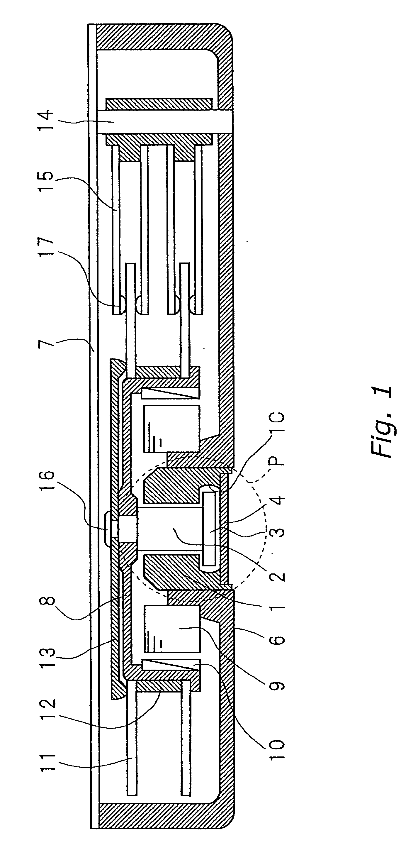
[0051]FIG. 1 is a cross-sectional view of an HDD, which is a disc recording and reproducing apparatus according to an embodiment of the present invention.

[0052] The HDD includes a base 6, an upper lid 7, a spindle motor, magnetic disc(s) 11, a spacer 12, a damper 13, a support 14, and rotation arms 15.

[0053] The spindle motor includes a hydrodynamic bearing device, a hub 8, a stator 9, and a magnet 10.

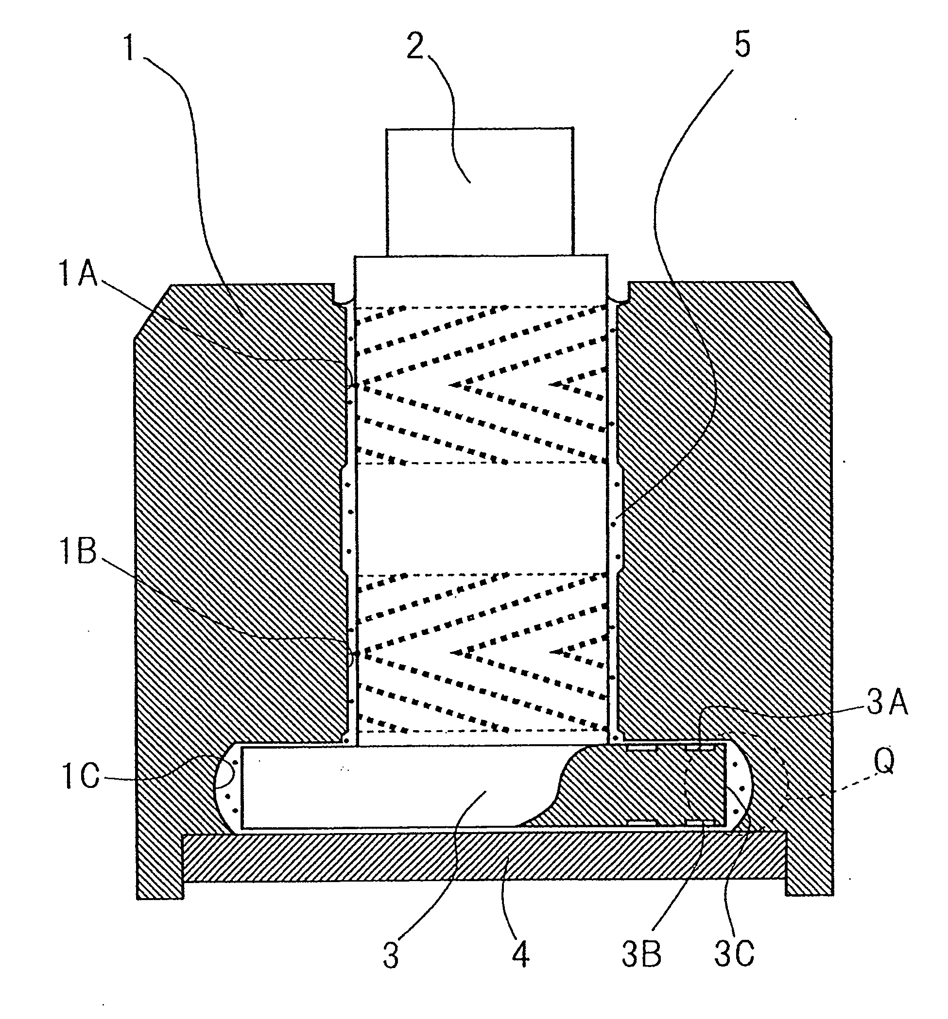
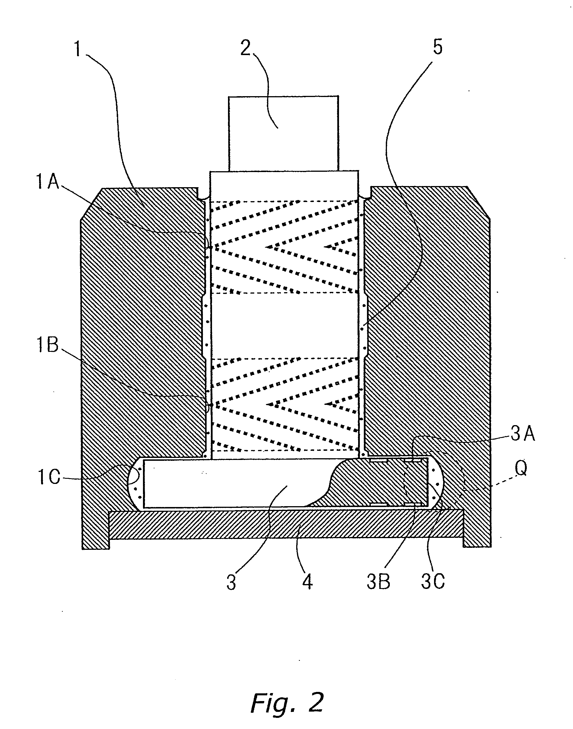
[0054] The hydrodynamic bearing device includes a sleeve 1, a shaft 2, a flange 3, and a thrust plate 4 (see circle P indicated by broken lines in FIG. 1).

[0055] The base 6 and the upper lid 7 are fitted to each other and form a housing of a box shape. The base 6 and the upper lid 7 seal the housing so that foreign materials such as dirt from outside can be prevented from entering.

[0056] The sleeve 1 is inserted into a hole of the base 6, and is fixed.

[0057] The sh...


PUM


Abstract

A hydrodynamic bearing device which realizes power saving, reduction of a time period necessary for stabilizing rotation, and enhancement in durability to startup and halting of the motor at the same time by accelerating circulation of a lubricant in the vicinity of a flange with loss torque being kept low is provided. A flange (3) is fixed to one end of a shaft (2). On an inner surface of one of openings of a sleeve (1), a step portion (1C) is provided. When the shaft (2) is inserted into the sleeve (1), the flange (3) is in close vicinity to the step portion (1C). An inner diameter of the step portion (1C) is smaller in end portions in an axial direction than in a central portion. Thus, a gap between an outer surface (3C) of the flange (3) and a surface of the step portion (1C) which opposes the outer surface (3C) is narrow in the vicinity of boundaries of the outer surface (3C) of the flange (3) than in the vicinity the central portion.

Description

BACKGROUND OF THE INVENTION [0001] 1. Field of the Invention [0002] The present invention relates to a hydrodynamic bearing device, a spindle motor using the same, and a disc recording and reproduction apparatus including the same. [0003] 2. Description of the Related Art [0004] The disc recording and reproducing apparatus may be, for example, a hard disc drive (HDD), or a DVD recorder, which magnetically or optically reads / writes data from / to a disc type recording medium such as a magnetic disc or an optical disc (hereinafter, referred to as a disc) while rotating the disc. [0005] Disc recording and reproducing apparatuses are required to have more capacity and a higher speed of data transfer. Particularly, more HDDs are used in AV equipment and mobile equipment in recent years. For use in such equipment, a high durability is also required in addition to the above requirements. Therefore, it is desired that rotation of the discs becomes more rapid and more stable with a high precis...

Claims


Application Information

Patent Timeline
IPC IPC(8): F16C32/06
CPCF16C33/107F16C17/107F16C2370/12
Inventor TOKUNO, YASUNORITAKASUKA, TOSHINORIIKEGAWA, TAIZO
Owner PANASONIC CORP
Features
  • Generate Ideas
  • Intellectual Property
  • Life Sciences
  • Materials
  • Tech Scout
  • Unparalleled Data Quality
  • Higher Quality Content
  • 60% Fewer Hallucinations
Learn More