Production paint shop design

a paint shop and production technology, applied in the direction of spray booths, pretreated surfaces, coatings, etc., can solve the problems of increasing the cost of paint, requiring a significant amount of advanced technology, and requiring hundreds of millions of dollars in advanced technology, so as to reduce the flow rate of particulate paint, improve the quality of paint finish, and improve the effect of paint finish

Inactive Publication Date: 2006-03-30
FUJIFILM HEALTHCARE CORP +1
View PDF42 Cites 74 Cited by
  • Summary
  • Abstract
  • Description
  • Claims
  • Application Information

AI Technical Summary

Benefits of technology

[0009] Two benefits are derived by moving the vehicles at a generally perpendicular direction in a longitudinal axis of the vehicles. First, the conveyor may be slowed down to half its conventional speed while processing the same vehicle rate, which will improve paint finish quality by enabling a reduction in the flow rate of particulate paint in the paint application equipment. Second, through processing vehicles upon a conveyor moving at its original rate enables twice as many vehicles to be processed. Furthermore, some combination of a partial reduction in line speed and a partial reduction in paint flow rate produces an improved paint finish while still increasing a vehicle processing rate through the paint application facility.
[0010] The novel paint application facility design associated with the present invention, uses a new conveyor orientation by moving the conveyors to the outer wall of the various paint application tanks and booths. Alternatively, the conveyors are located outside the booth eliminating all contact of the conveyors with the particulate paint being applied to the vehicle bodies. In either case, an improved airflow quality is derived inside the paint booth which results in improved paint quality and a reduction in paint defects.

Problems solved by technology

Painting automobile bodies has progressed to require a significant amount of advanced technology housed in painting facilities costing of hundreds of millions of dollars.
A typical paint facility requires up to a third or more of an assembly plant floor space, which is exceedingly costly adding to the cost of painting a vehicle body in terms of both facility construction and energy requirements for maintaining the paint facility.
None of the prior art patents have addressed the need to reduce the overall paint application facility size by reducing the size of the various paint booths and ovens required to apply and secure subsequent paint coatings such as, for example, primer surfacer, base coat, and clear coat.
However, much of this overspray is known to adhere to the conveyor, which results in frequent cleaning.
This is known to result in contaminants in the paint application booth causing defects in the paint coating.
Locating process equipment inside the booth is known to cause turbulent airflow.
However, no attempts have been made to reduce the impact of the conveyor upon the airflow through the booth.

Method used


Image

  • Production paint shop design
  • Production paint shop design
  • Production paint shop design

Examples


Embodiment Construction

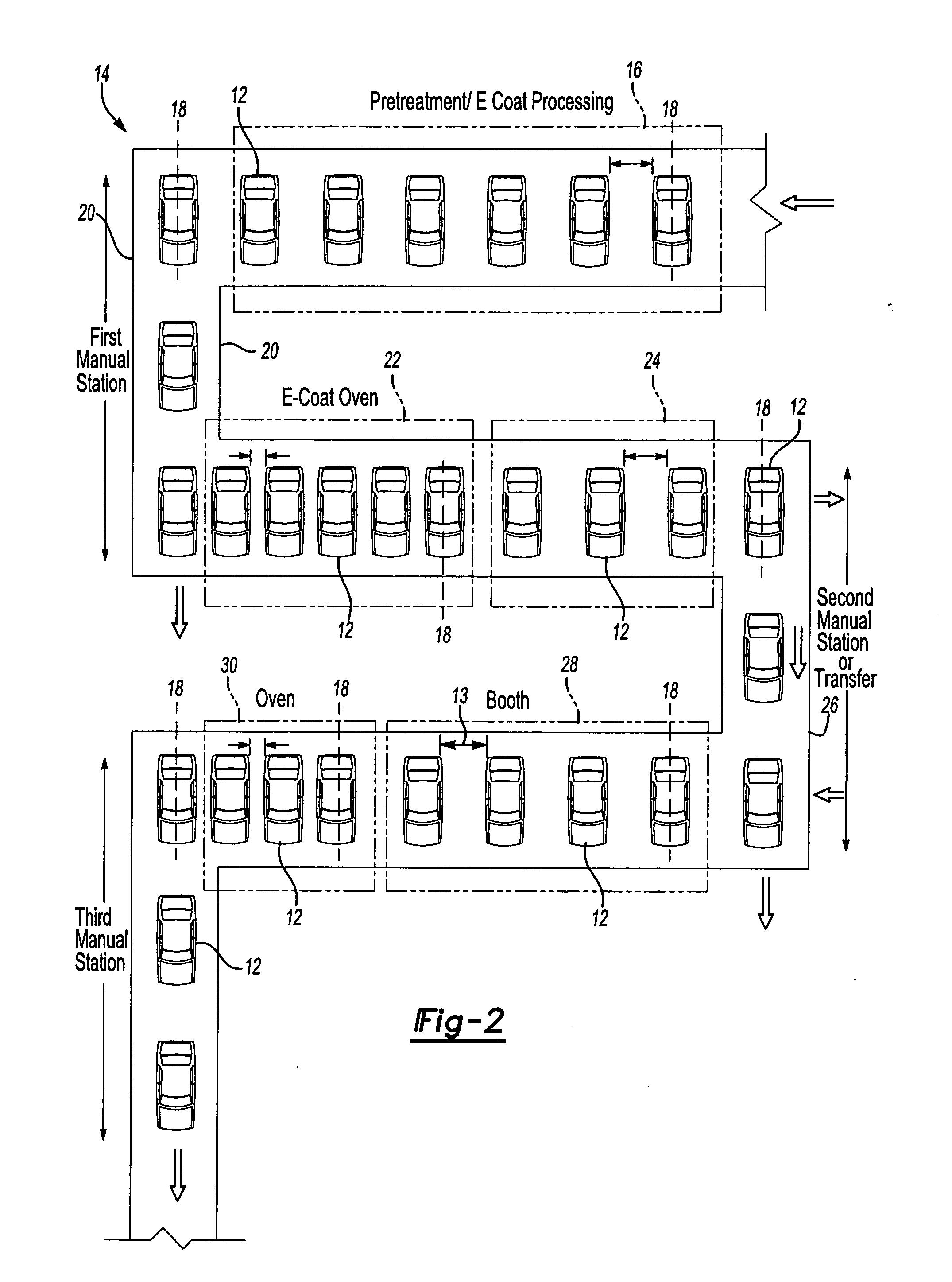
[0022] Referring to FIG. 2, one preferred arrangement of the inventive paint application facility is generally shown at 14. In this embodiment, like conventional paint application facilities, vehicle bodies 12 are initially introduced to the paint application facility from a body fabrication shop (not shown). The first processing step of the vehicle bodies 12 are processed in pretreatment and electrodeposition coating tanks. As is known to those of skill in the art, a pretreatment station cleans and treats the vehicle body, known as body-in-white, with a phosphate coating to improve paint adhesion and reduce corrosion of the vehicle body. The pretreatment station uses several immersion and spray clean, rinse, and conversion tanks to apply a high quality phosphate coating to the body-in-white. Subsequent to the pretreatment station, the vehicle body 12 is cleansed with deionized water and submerged in an electrodeposition tank where electrocoat paint is applied.

[0023] The vehicle bo...


PUM


Abstract

A paint application facility including a paint booth assembly for applying paint to automotive vehicles each defining a longitudinal axis includes a carrier adapted to serially move a plurality of automotive vehicles through the booth assembly in a direction generally perpendicular to the longitudinal axis of the vehicle.

Description

BACKGROUND OF THE INVENTION [0001] Painting automobile bodies has progressed to require a significant amount of advanced technology housed in painting facilities costing of hundreds of millions of dollars. These paint facilities receive unfinished “body in white” vehicle bodies from a body shop for paint processing and transfer painted and sealed bodies to final assembly facilities where the vehicle is completely assembled. A typical paint facility requires up to a third or more of an assembly plant floor space, which is exceedingly costly adding to the cost of painting a vehicle body in terms of both facility construction and energy requirements for maintaining the paint facility. [0002] Various attempts have been made to adjust the processing orientation of vehicle bodies through paint shops. However, the primary focus of these concepts are directed toward pretreatment and electro deposition primer tanks. One such concept is shown in U.S. Pat. No. 6,419,983, Method of Introducing ...

Claims


Application Information

Patent Timeline
Patent Type & Authority Applications(United States)
IPC IPC(8): B05C13/00B05B15/12
CPCB05B13/0221B05B13/0442B05B13/0452B05B15/1207B65G2201/0294B05B15/1262B05B15/1292B65G49/0459B05B15/1214B05B14/46B05B16/20B05B16/40B05B16/95
Inventor COLE, DAVID J.
Owner FUJIFILM HEALTHCARE CORP
Why Eureka
Try Eureka