
Flatness monitor

Inactive Publication Date: 2006-04-06
ARCELORMITTAL DOFASCO
View PDF19 Cites 23 Cited by
  • Summary
  • Abstract
  • Description
  • Claims
  • Application Information

AI Technical Summary

Benefits of technology

[0007] Preferably, the image may be processed to provide a quantative i

Problems solved by technology

Whilst the flatness of the body of a steel strip can be maintained, the edges of such a strip are prone to deviate during the production of the strip and produce what is known as a “rippled” edge.
This rippling, if beyond certain limits, can adversely impact upon the subsequent processing of the strip, and lead to failure of the can.
These measuring techniques, however, are relatively laborious and subjective, and do not lend themselves to continuous monitoring and a quantative evaluation of the edge.

Method used


Image

  • Flatness monitor
  • Flatness monitor
  • Flatness monitor

Examples


Embodiment Construction

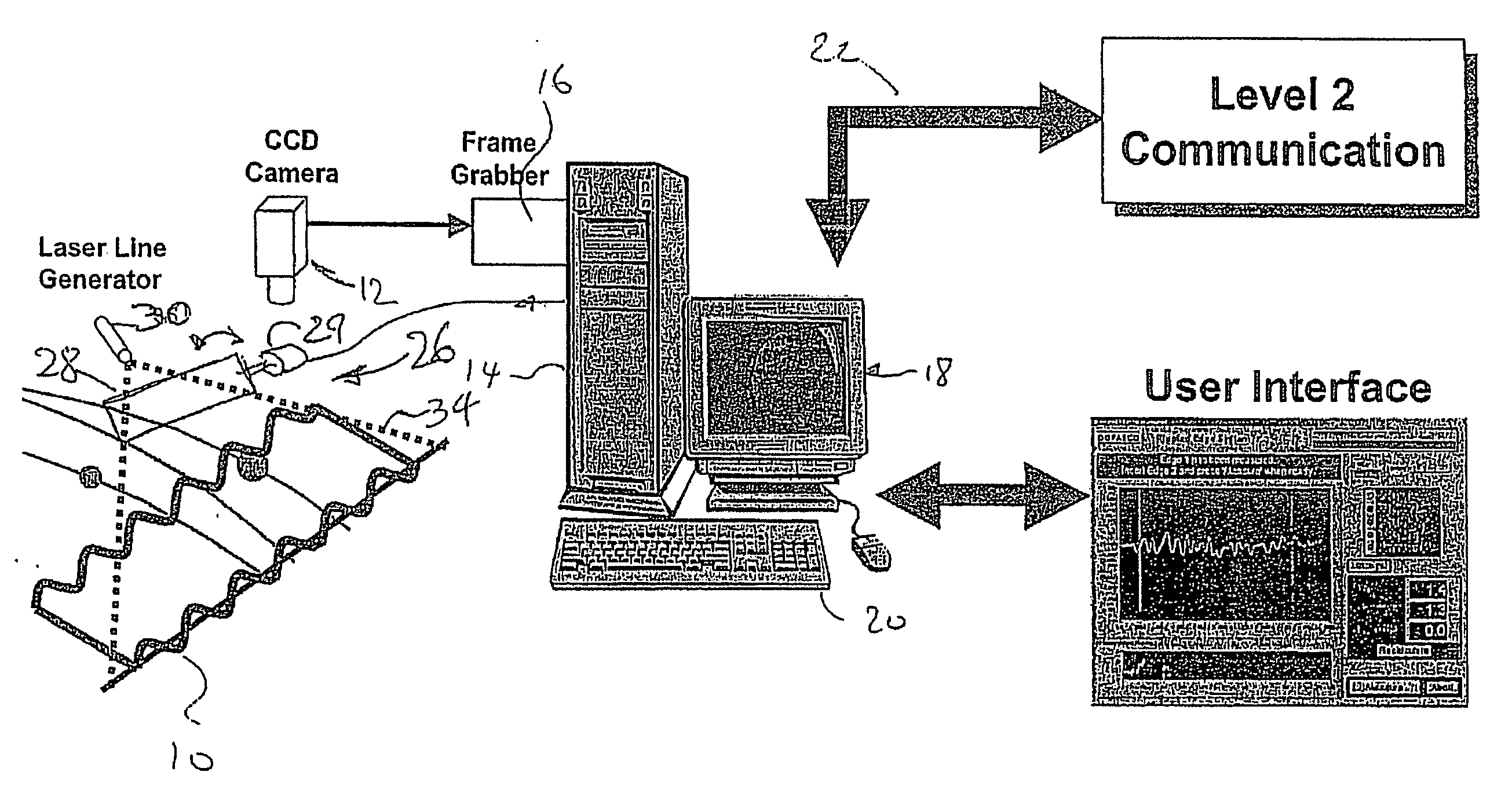
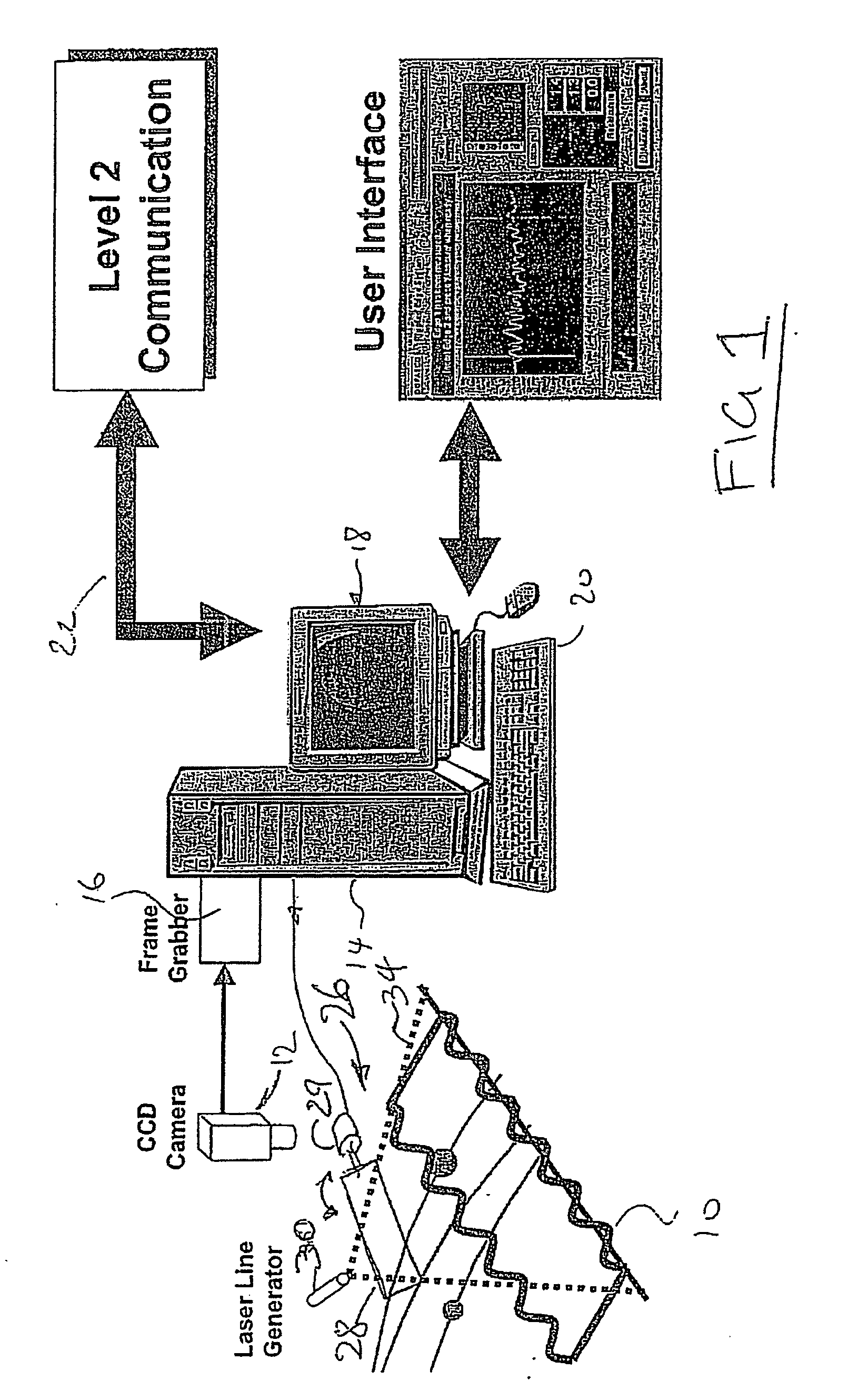
[0019] Referring therefore to FIG. 1, a sample of steel strip 10 whose flatness is to be assessed is supported beneath a camera 12. The camera 12 is connected to a computer 14 having image processing software 16. The computer 14 is connected to a user interface 18 and an input device 20 to control the image produced on the interface 18. The computer 14 may also connect to auxiliary communications related to process control systems as indicated generally at 22.

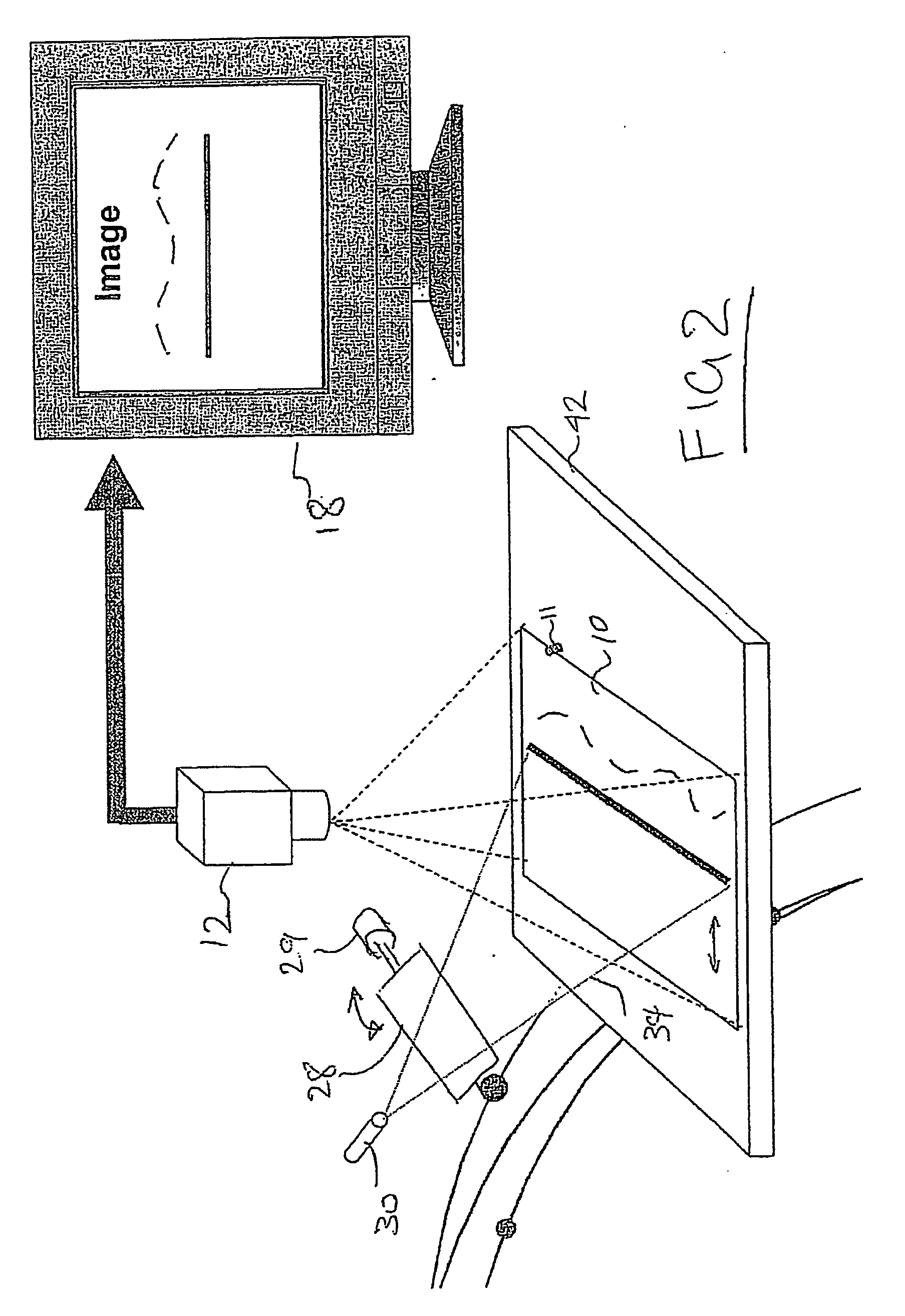
[0020] A scanner assembly 26 includes a scanning mirror 28 driven by a galvonometer 29 controlled by the computer 14. A coherent radiation source, e.g., a laser device 30, includes a lens to produce a fan shaped optical beam 34 that produces a line on a surface. The laser 30 is positioned such that the beam 34 intercepts the surface of the mirror 28 and is reflected on to the sample 10 at an angle to the optical axis of the camera 12. The point of impingement of the beam 34 on the sample 10 is controlled by the orientation of ...


PUM

PropertyMeasurementUnit
Widthaaaaaaaaaa
Dimensionaaaaaaaaaa
Heightaaaaaaaaaa

Abstract

A system method of monitoring flatness of a material. A beam of coherent light is projected on to a surface of the material to provide a line on the surface. An image of the line on the surface is obtained, and the image is used to determine a deviation of the line from a predetermined configuration. The deviation corresponds to an irregular pattern or unevenness of the material.

Description

This application claims priority from U.S. Patent Application Ser. No. 60 / 588,355 filed on Jul. 16, 2004.FIELD OF THE INVENTION [0001] The present invention relates to a method and apparatus for monitoring the flatness of a material. BACKGROUND OF THE INVENTION [0002] The flatness of a material is a paramount importance in certain applications. For example, in the steel industry, the flatness of a thin steel strip is critical to the effectiveness of subsequent processing. For example, such a strip of steel might be used in the manufacturer of cans, and the integrity of the tin coating process is dependent upon the flatness of the feed stock. [0003] Whilst the flatness of the body of a steel strip can be maintained, the edges of such a strip are prone to deviate during the production of the strip and produce what is known as a “rippled” edge. This rippling, if beyond certain limits, can adversely impact upon the subsequent processing of the strip, and lead to failure of the can. [000...

Claims


Application Information

Patent Timeline
IPC IPC(8): B21B37/28
CPCB21B38/02G01B11/306G01N21/8851G01N21/89G01N2021/8918G01N2021/8924
Inventor NIEMINEN, JOHNCHUPIL, VICTORLAMMERS, PAULSLOAN, DAVID
Owner ARCELORMITTAL DOFASCO
Features
  • Generate Ideas
  • Intellectual Property
  • Life Sciences
  • Materials
  • Tech Scout
  • Unparalleled Data Quality
  • Higher Quality Content
  • 60% Fewer Hallucinations
Learn More