2D central difference level set projection method for ink-jet simulations

a projection method and inkjet technology, applied in the field of inkjet simulations, can solve the problems of increasing the complexity of the code required to do the taylor's extrapolation in both time and space and the upwind procedure, and the local riemann problem may not have simple solutions, so as to improve the performance facilitate code implementation, and improve the effect of the central difference schem

Active Publication Date: 2006-04-06
KATEEVA
View PDF8 Cites 12 Cited by
  • Summary
  • Abstract
  • Description
  • Claims
  • Application Information

AI Technical Summary

Benefits of technology

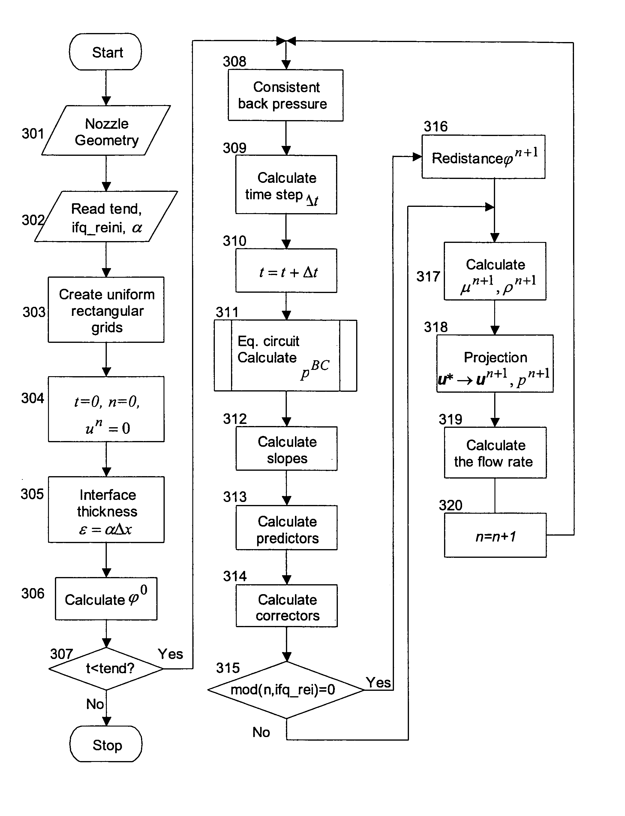
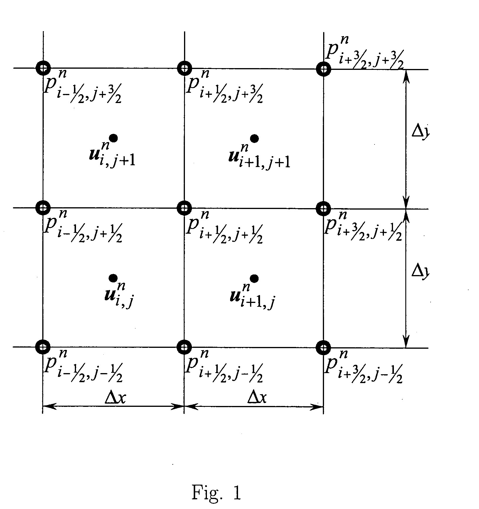
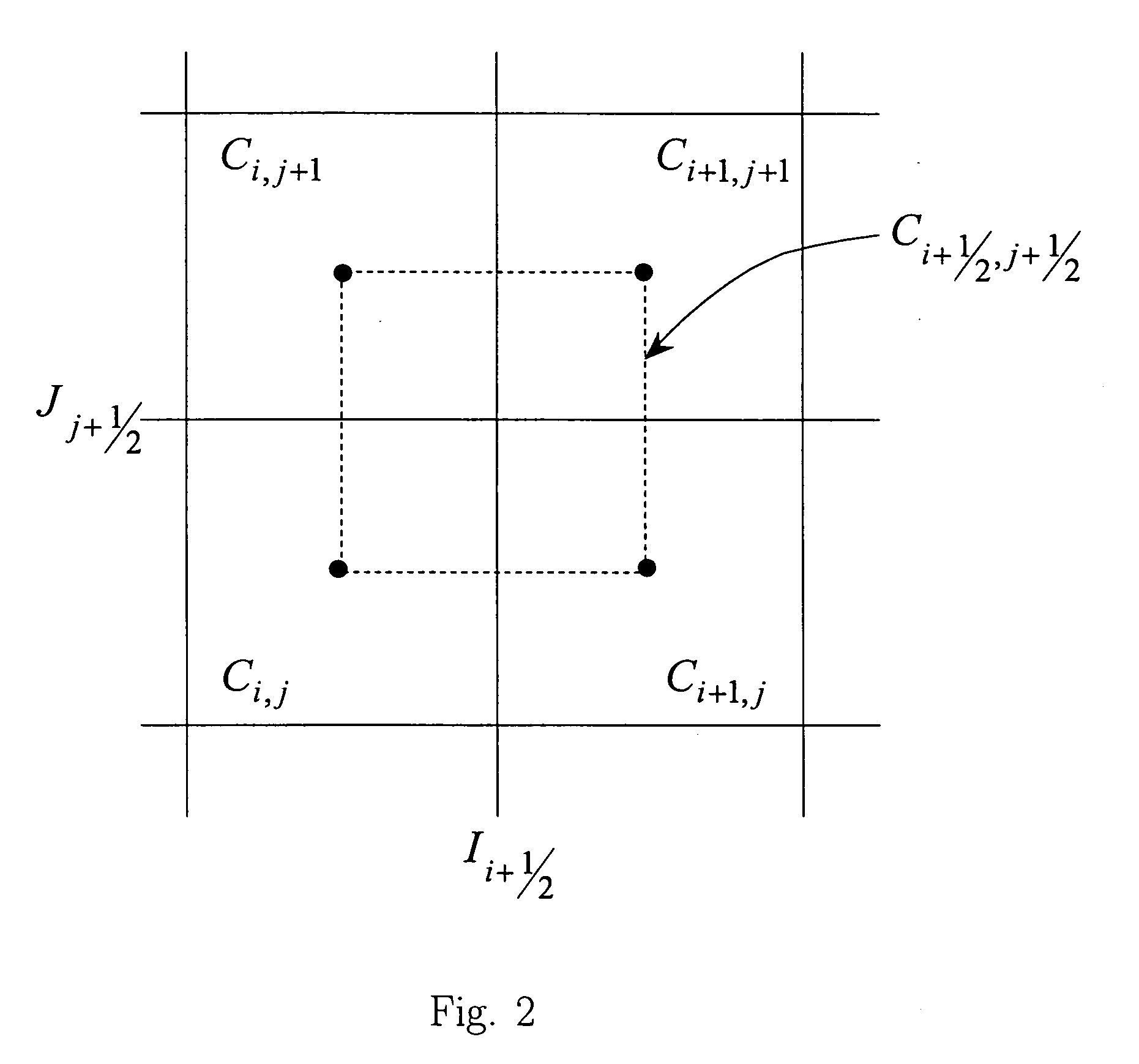
[0008] In the central difference scheme of this invention, the Navier-Stokes equations are again first solved in each time step without considering the condition of incompressibility. Then, the obtained velocity is “projected” into a space of divergence-free field. But, in contrast to the upwind scheme of the related application, the central difference scheme here uses staggered cell averages and the direction of local velocity is not important. Taylor's extrapolation in time is still used in calculating the time-centered velocity and level set predictors. But since it is only an extrapolation in time, the code implementation is much easier. One characteristic of the scheme is, if at time step t=tn the velocities and level set are located at cell centers, they will be located at grid points at the next time step t=tn+1. The velocities and level set will be at cell centers again at time step t=tn+2. That the velocities and level set alternate locations over the series of time steps is why the method is described as using “staggered” grids.
[0009] To im...

Problems solved by technology

However, if the fluid is not a Newtonian fluid, the local Riemann problem may not have simple solutions, and the Godunov upwind procedure would be very difficult...

Method used


Image

  • 2D central difference level set projection method for ink-jet simulations
  • 2D central difference level set projection method for ink-jet simulations
  • 2D central difference level set projection method for ink-jet simulations

Examples


Embodiment Construction

[0029] I. Introduction

[0030] This invention is regarding the development of a central difference level set projection method on uniform rectangular grids for two-dimensional two-phase flow, especially ink jet, simulations. The Navier-Stokes equations are first solved in each time step without considering the condition of incompressibility. The obtained velocity is then “projected” into a space of divergence-free field. In contrast to the upwind scheme of the related application, the central difference scheme here uses staggered cell averages and the direction of local velocity is not important. To solve the Navier-Stokes equations, the velocity and level set slopes are first calculated. Taylor's extrapolation in time is used in calculating the time-centered velocity and level set predictors. These predictors are then employed to calculate the velocity corrector, which is not divergence-free.

[0031] One characteristic of the scheme is, if at time step t=tn the velocities and level s...


PUM


Abstract

A coupled level set projection method is incorporated into a finite-difference-based ink-jet simulation method to make the simulation easier and faster to run and to decrease the memory requirements. The coupled level set projection method is based on a central difference discretization on uniform rectangular grids. A constructed numerical projection operator, in the form of either a finite difference projection operator or a finite element projection operator, can be used in the central difference scheme, in which case the resulting linear systems can be solved by a multi-grid method. The finite difference projection operator is used when the fluid velocity is located at grid points and the pressure at cell centers, whereas the finite element projection operator is used when the fluid velocity is located at cell centers and the pressure at grid points.

Description

RELATED APPLICATION DATA [0001] This application is related to application Ser. No. 10 / 390,239, filed on Mar. 14, 2003 and entitled “Coupled Quadrilateral Grid Level Set Scheme for Piezoelectric Ink-Jet Simulation.” The disclosure of this related application is incorporated herein by reference and referred to in the following description as “related application.”BACKGROUND OF THE INVENTION [0002] 1. Field of the Invention [0003] The present invention relates to an improved model and accompanying algorithm to simulate and analyze ink ejection from a piezoelectric print head. The improvements to the simulation model and algorithm include the development of a central difference scheme for the coupled level set projection method for two-phase flows, and also to the construction of multi-grid-compatible discrete projection operators that can be used in the central difference scheme. The simulation model and algorithm may be embodied in software and run on a computer, with the time-elapse...

Claims


Application Information

Patent Timeline
IPC IPC(8): E21B47/10
CPCG06F17/5018G06F2217/16G06F2111/10G06F30/23G06G7/48
Inventor YU, JIUN-DER
Owner KATEEVA
Why Eureka
Try Eureka