Temperature gradient detector

a detector and temperature gradient technology, applied in the field of temperature gradient detectors, can solve problems such as impracticality of methods, and achieve the effects of long shelf life, simple, and inexpensive production

Inactive Publication Date: 2006-04-06
FRADEN JACOB
View PDF4 Cites 24 Cited by
  • Summary
  • Abstract
  • Description
  • Claims
  • Application Information

AI Technical Summary

Benefits of technology

[0007] Another object of the invention is to provide a temperature gradient detector that is simple, inexpensive to produce, doesn't require calibration, has long shelf life and can be sterilized without degrading its' performance.

Problems solved by technology

However, when the equipment is moving, or ambient conditions are not suitable for the IR monitoring, or, in medicine, when a continuous monitoring is required from a patient's body surface, this method is impractical.

Method used


Image

  • Temperature gradient detector
  • Temperature gradient detector
  • Temperature gradient detector

Examples


Embodiment Construction

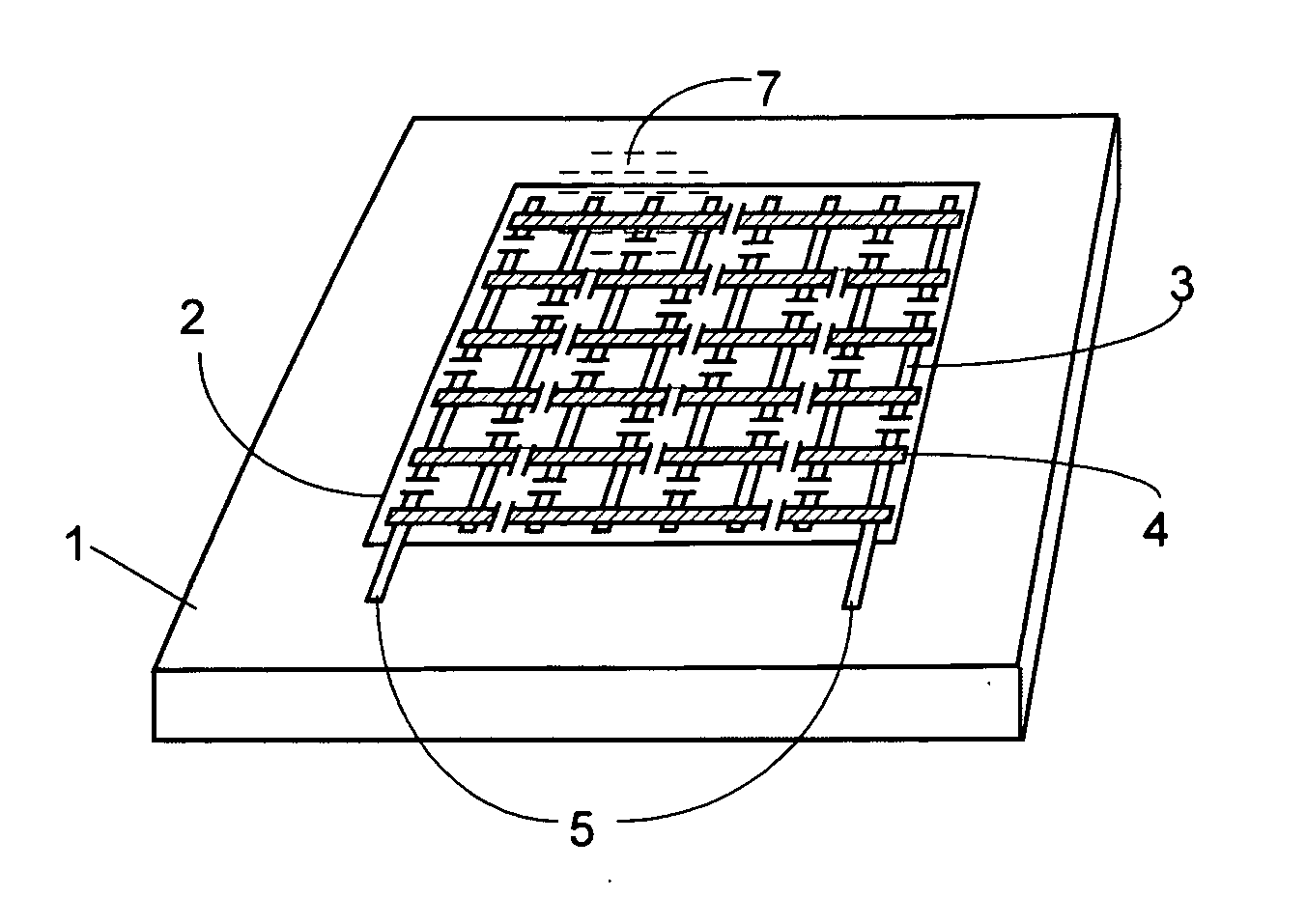
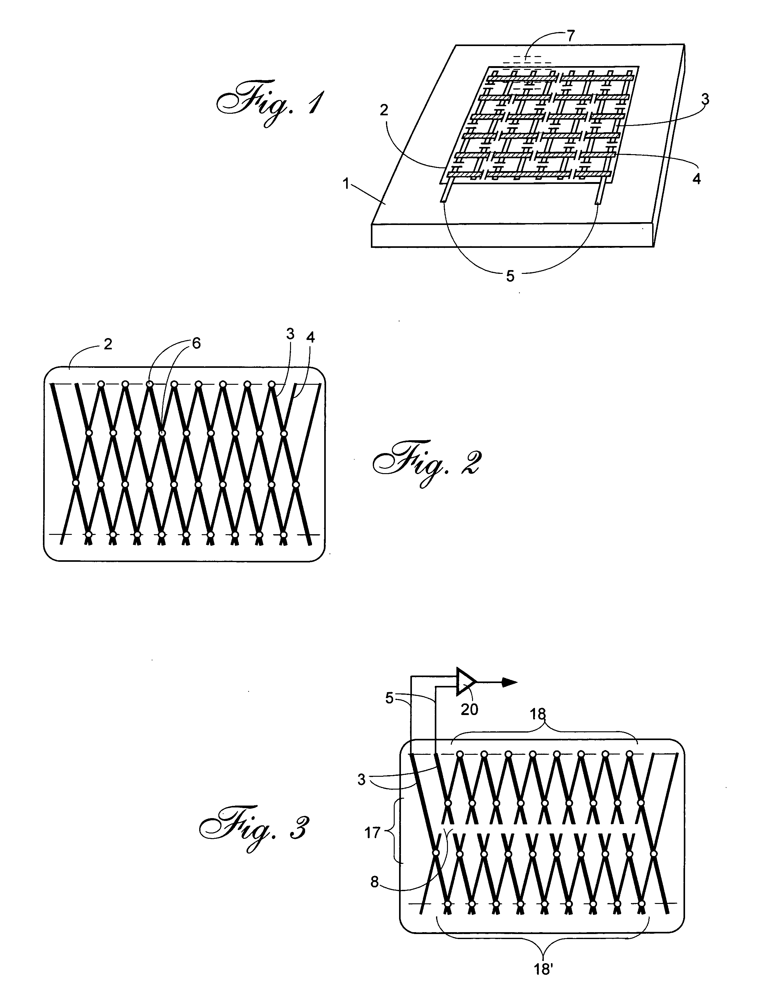
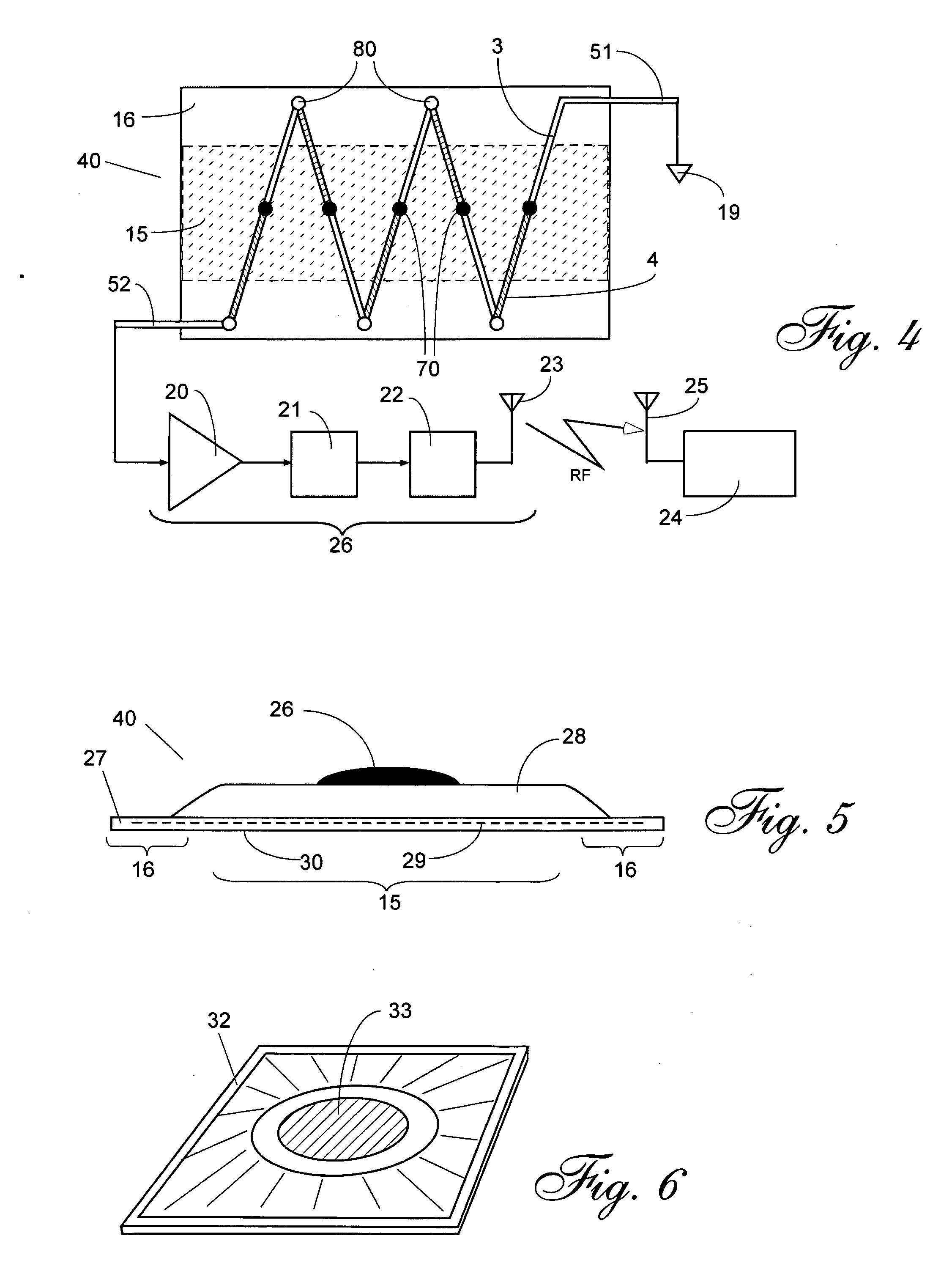
[0017] Several methods of a contact detection of thermal gradients are known in art. Some are based on use of absolute temperature sensors such as thermistors or RTDs, some use the IR emission detectors. However, temperature detectors belonging to a class of relative sensors appear to be more suitable for the task. A relative sensor by definition responds to a temperature difference between different parts of the sensor. The most popular is a sensor based on a thermoelectric effect, better known as a thermocouple. The variance of a thermocouple is a thermopile which is a serially connected multiple thermocouple junctions. Thermopiles are better known by their designs used for the mid and far infrared detection (See J. Fraden, Handbook of Modern Sensors. Springer Verlag. 3rd ed., 2004). A thermopile was originally invented by Joule for the purpose of increasing the output signal of a thermocouple. Each thermocouple consists of two dissimilar conductors which are joined together at tw...


PUM


Abstract

To monitor temperature variations over a surface, the present invention employs a grid of thermoelectric wires imbedded into a carrier or body patch. The thermoelectric wires form a thermopile with “hot” junctions distributed over the central section of the body patch, while the “cold” junctions” are positioned at the periphery of the patch. The patch may be a wound dressing application. The thermopile is connected to an amplifier and subsequently to a threshold detector. Crossing a threshold activates a radio transmitter that sends a signal to a remote receiver. The carrier (patch) is applied to a monitored surface (examples are machinery enclosures and patient skin or wound) in such a manner that the peripheral portion of the patch is outside of the monitored area.

Description

FIELD OF INVENTION [0001] The present invention relates to sensors for continuous monitoring of temperature gradients being developed over an object's surface and specifically to medical sensors for monitoring development of cutaneous or subcutaneous thermogenic inflammations. It is based on U.S. Provisional Patent Application No. 60 / 615,388 filed on Oct. 4, 2004. DESCRIPTION OF PRIOR ART [0002] Detection of temperature gradients in industrial applications may help to uncovers troublesome conditions that are manifested in increased heat production or heat conduction at a specific surface of a machinery or equipment. Examples include measuring hot spots in engines where excessive friction results in heat production. This condition should be detected before it may cause a damage. [0003] In medical applications, subcutaneous and even cutaneous injuries or inflammations may lead to pyrogenic processes. In other words, surface temperature increases with infection or injury. In veterinary...

Claims


Application Information

Patent Timeline
Patent Type & Authority Applications(United States)
IPC IPC(8): H01L35/28
CPCA61B5/015G01K7/04
Inventor FRADEN, JACOB
Owner FRADEN JACOB
Why Eureka
Try Eureka