Steam valve

a technology of steam valve and valve body, which is applied in the direction of fluid pressure control, separation processes, instruments, etc., can solve the problems of direct impact on the wire-net screen, wire net will be broken, and provide a significant matter of defectiv

Active Publication Date: 2006-04-06
KK TOSHIBA
View PDF5 Cites 21 Cited by
  • Summary
  • Abstract
  • Description
  • Claims
  • Application Information

AI Technical Summary

Benefits of technology

[0017] The present invention was conceived to substantially eliminate defects or drawbacks encountered in the prior art mentioned above and an object of the present invention is to provide a steam valve having a screen, with high strength, circumferentially mounted to a strainer and being capable of reliably removing even fine particulate impurities.
[0030] According to the steam valve of the present invention of the structure mentioned above, either the permanent screen unit only, or both the permanent screen unit and the temporary screen unit are mounted to the body of the strainer, and each of the permanent screen unit and the temporary screen unit is formed to provide a cylindrical or substantially cylindrical structure made of a perforated plate. The perforations of the cylindrical permanent screen unit and temporary screen unit are arranged such that the center of each perforation corresponds to each vertex of a regular triangle, and as a result, a space ratio can be freely set. In addition, if a material with increased strength is selected for the plate, the screen can realize a strength required for withstanding shock caused by the main steam.

Problems solved by technology

However, thermal shock caused by ultra-high pressure and very-high temperature steam has a direct impact on a wire-net screen.
Therefore, with years of use, the wire net is expanded, contracted, or loosened, producing vibration or noise, and finally, the wire net will be broken, providing a significant matter of defective.
This results in a decrease in the allowable stress of a screen.
Although such defect may be eliminated by strengthening the screen, if the diameter of each wire of the wire net is increased, the mesh size is inevitably large and fine or minute impurities are thus not removed.

Method used


Image

  • Steam valve
  • Steam valve
  • Steam valve

Examples


first embodiment

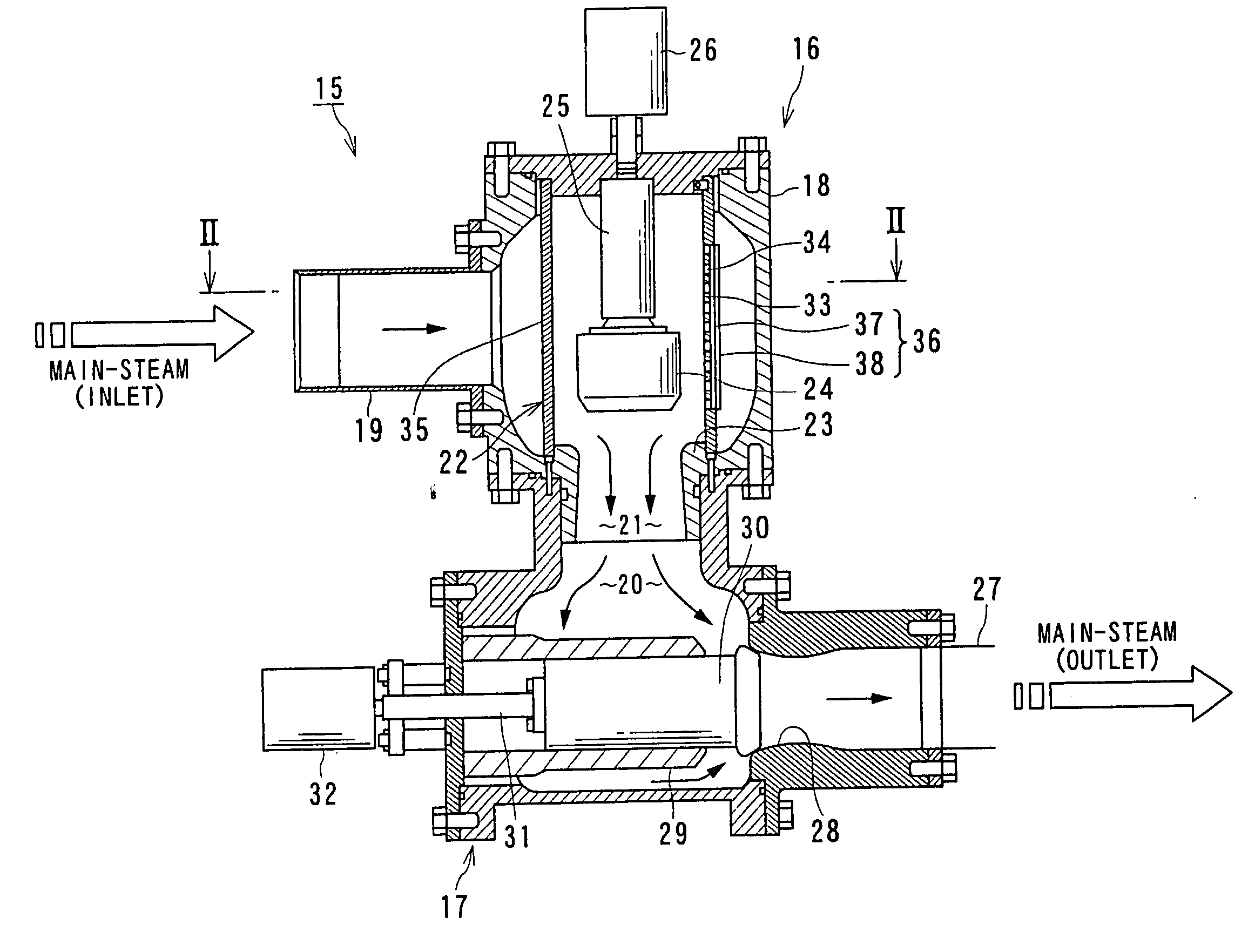
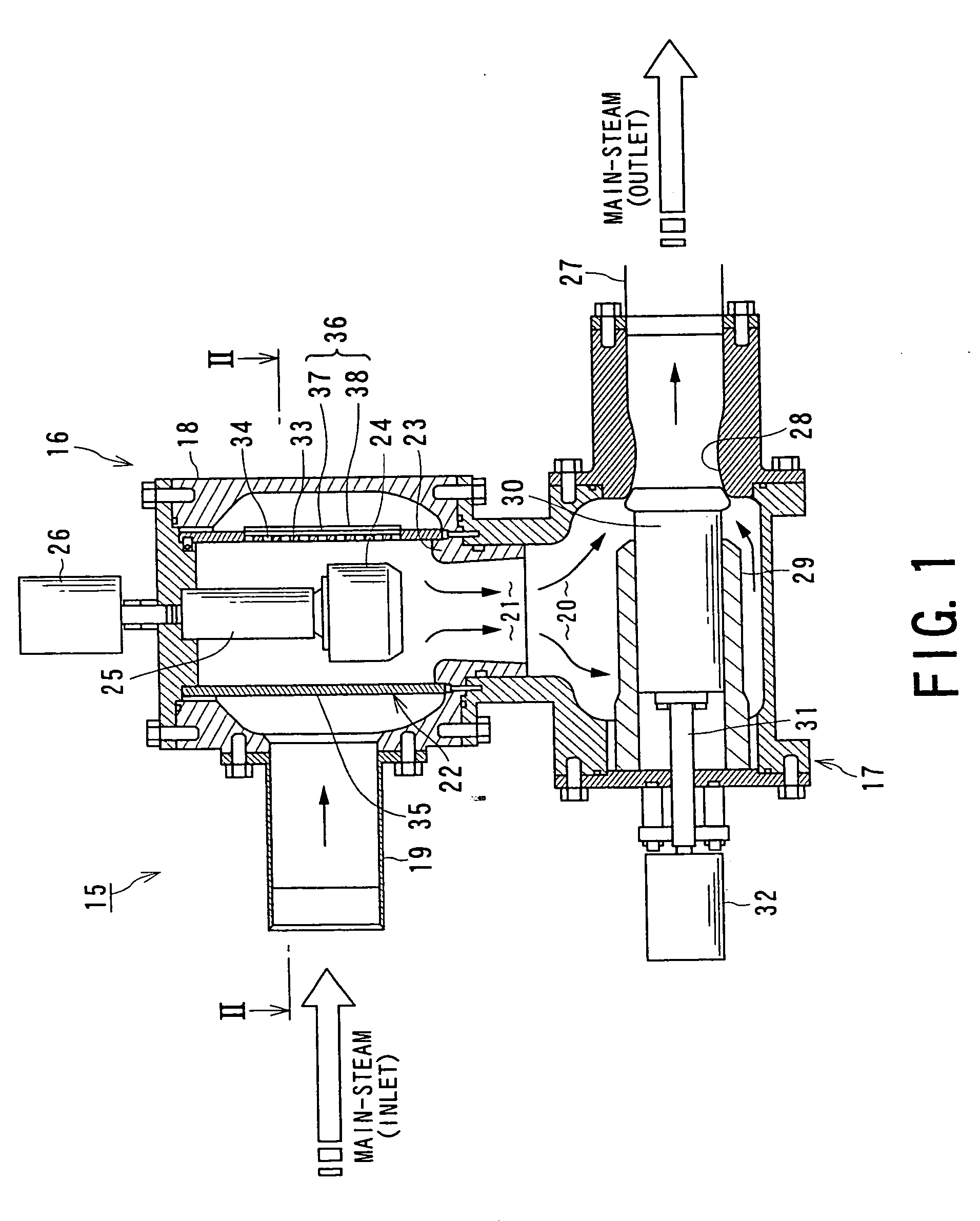
[0044] With reference to FIG. 1 showing a steam valve according to the present invention, a steam valve 15 is a large valve having a combined structure in which, for example, a main-steam stop valve unit and a steam-regulation valve unit are accommodated in a single valve casing.

[0045] The steam valve 15 in this embodiment has a first valve unit 16, which corresponds to the main-steam valve unit, arranged upstream of a main steam flow and a second valve unit 17, which corresponds to the steam-regulation valve unit, arranged downstream of the first valve unit 16. The first valve unit 16 and the second valve unit 17 are accommodated in a single or common valve casing 18.

[0046] The first valve unit 16 has a first main-steam inlet 19 in the valve casing 18 and a first main-steam outlet 21 communicated with a second main-steam inlet 20 of the second valve unit 17. In the first valve unit 16, a cylindrical strainer 22 for removing impurities, such as oxide scale, is accommodated.

[0047] ...

second embodiment

[0066]FIGS. 5 and 6 show concepts of a steam valve according to the present invention, in which FIG. 5 is a fragmentary longitudinal sectional view of the steam valve in this embodiment, and FIG. 6 is a plan view, looking from the arrows VI in FIG. 5.

[0067] In the steam valve of this embodiment, the rivets 41 are inserted through the strainer body 33 after the permanent screen unit 37 and the temporary screen unit 38 are mounted to the strainer body 33 so as to fix and support the permanent screen unit 37 and the temporary screen unit 38 circumferentially mounted to the strainer body 33 of the strainer 22. In this embodiment, furthermore, in order to simplify the operation of demounting the temporary screen unit 38, the temporary screen unit 38 has openings 43 through which heads 42 of the rivets 41 can readily pass. The openings 43 formed in the temporary screen unit 38 may be replaced with spot-faced holes.

[0068] In a known steam valve, in order to mount the permanent screen unit...

third embodiment

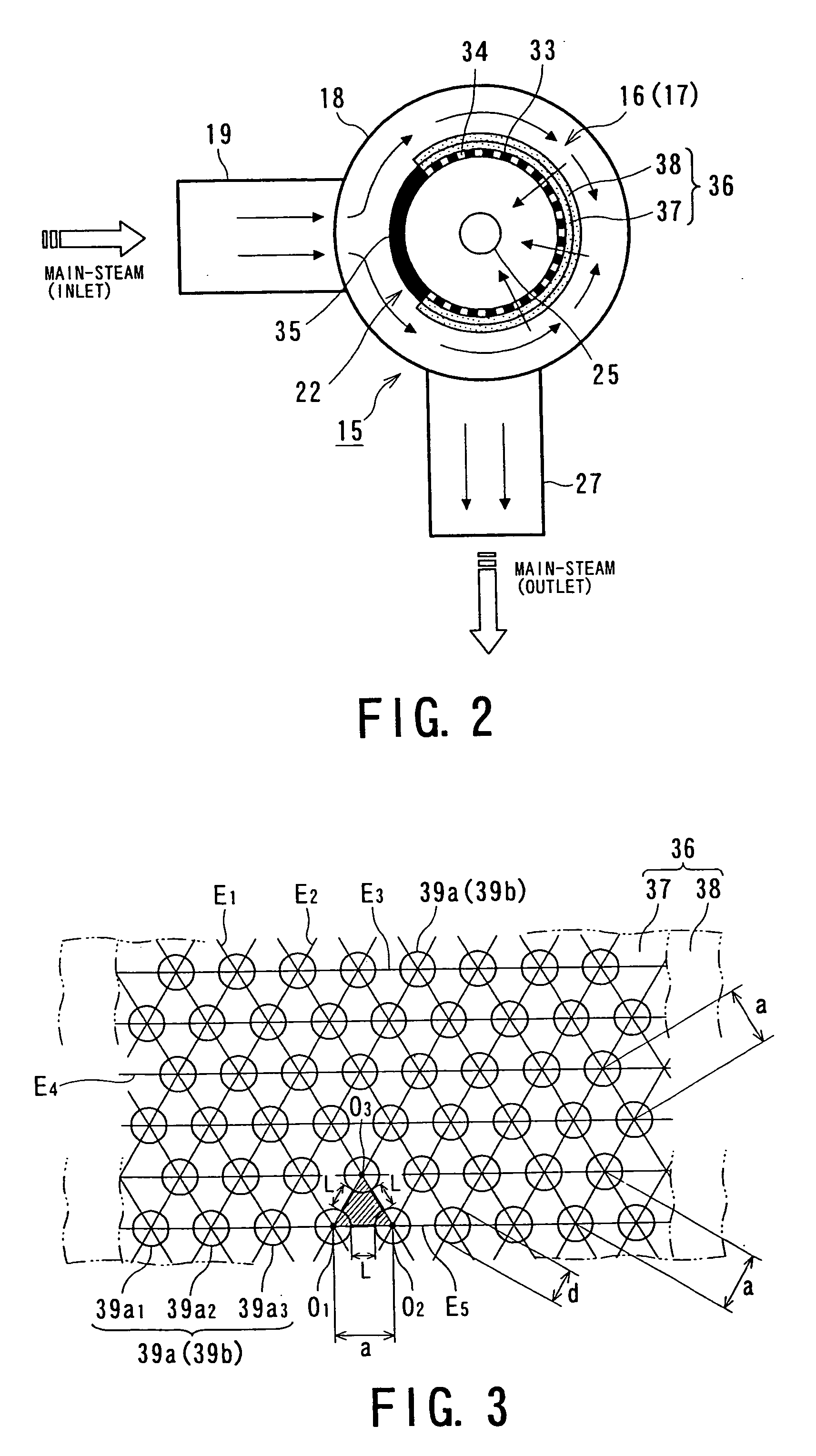
[0072]FIG. 7 is a developed view of a steam valve according to the present invention.

[0073] In the steam valve of this embodiment, at a time of mounting the permanent screen unit 37 and the temporary screen unit 38 to the strainer body 33, the perforations 39a of the permanent screen unit 37 and the perforations 39b of the temporary screen unit 38 are displaced in positions from each other.

[0074] In this embodiment, as described above, since the perforations 39a of the permanent screen unit 37 and the perforations 39b of the temporary screen unit 38 are displaced from each other in the circumferential direction, a space ratio, which indicates a ratio with respect to main steam that passes through the screen, can be set to a desired optional value.


PUM

PropertyMeasurementUnit
temperatureaaaaaaaaaa
pressureaaaaaaaaaa
diameteraaaaaaaaaa

Abstract

In a steam valve, a strainer is arranged between a valve body and a valve casing in which the valve body is accommodated, and a screen assembly is mounted on an outer peripheral portion of the strainer. The screen assembly includes a temporary screen unit and a permanent screen unit which is arranged inside the temporary screen unit. Each of the screen units is a substantially cylindrical structure made of a plate formed with perforations.

Description

BACKGROUND OF THE INVENTION [0001] 1. Field of the Invention [0002] The present invention relates to a steam valve used in a steam turbine plant or like, and more particularly, to a steam valve having an improved strainer accommodated in a valve casing and adapted to remove impurities, or foreign objects or materials contained in steam. [0003] 2. Related Art [0004] Generally, steam-turbine plants have many steam valves having different diameters in accordance with their functions or applications. In these steam valves, a main-steam stop valve and a steam-regulation valve, for example, both of which are provided between a steam turbine and a steam generator, such as a boiler, are inevitably very large pressure-resistant valves since both valves are exposed to ultra-high-pressure (16.6 MPa to 24.1 MPa) and very-high-temperature (538° C. to 566° C.) steam. [0005] Such a very large main-steam stop valve or steam-regulation valve, which is exposed to ultra-high-pressure and very-high-tem...

Claims


Application Information

Patent Timeline
Patent Type & Authority Applications(United States)
IPC IPC(8): B01D35/00
CPCB01D46/2403B01D46/4272B01D2275/10F16K47/08Y10T137/7976Y10T137/8085Y10T137/86734Y10T137/87917
Inventor TAKEMARU, RYUHEI
Owner KK TOSHIBA
Why Eureka
Try Eureka