
Process and device for the thermal stimulation of gas hydrate formations

a gas hydrate and thermal stimulation technology, applied in separation processes, wellbore/well accessories, insulation, etc., can solve the problems of limited treatment of gas hydrates, ineffective and energy-intensive processes, and only possible introduction of hot media, so as to achieve optimal thermal transfer, high gas flow rate, and effective exploration of gas hydrate formations

Inactive Publication Date: 2006-04-06
GEOFORSCHUNGSZENT POTSDAM A CORP OF GERMANY
View PDF5 Cites 10 Cited by
  • Summary
  • Abstract
  • Description
  • Claims
  • Application Information

AI Technical Summary

Benefits of technology

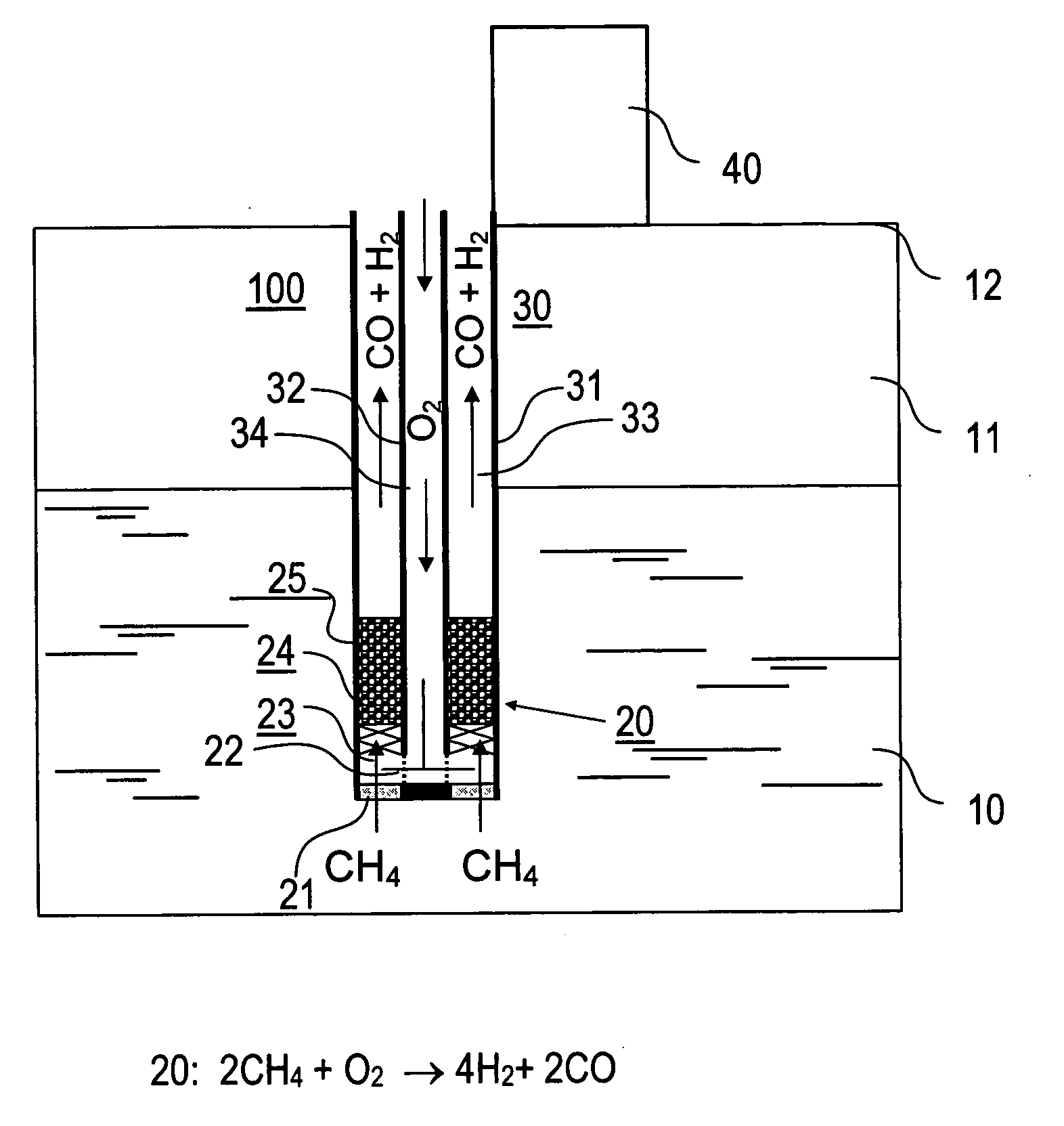
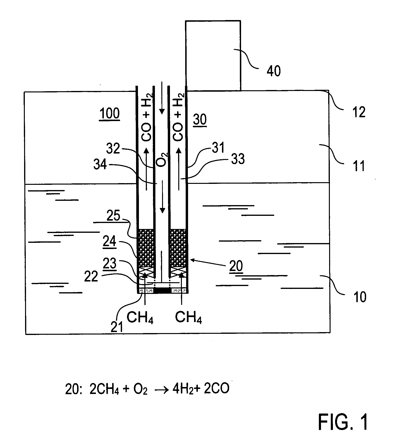
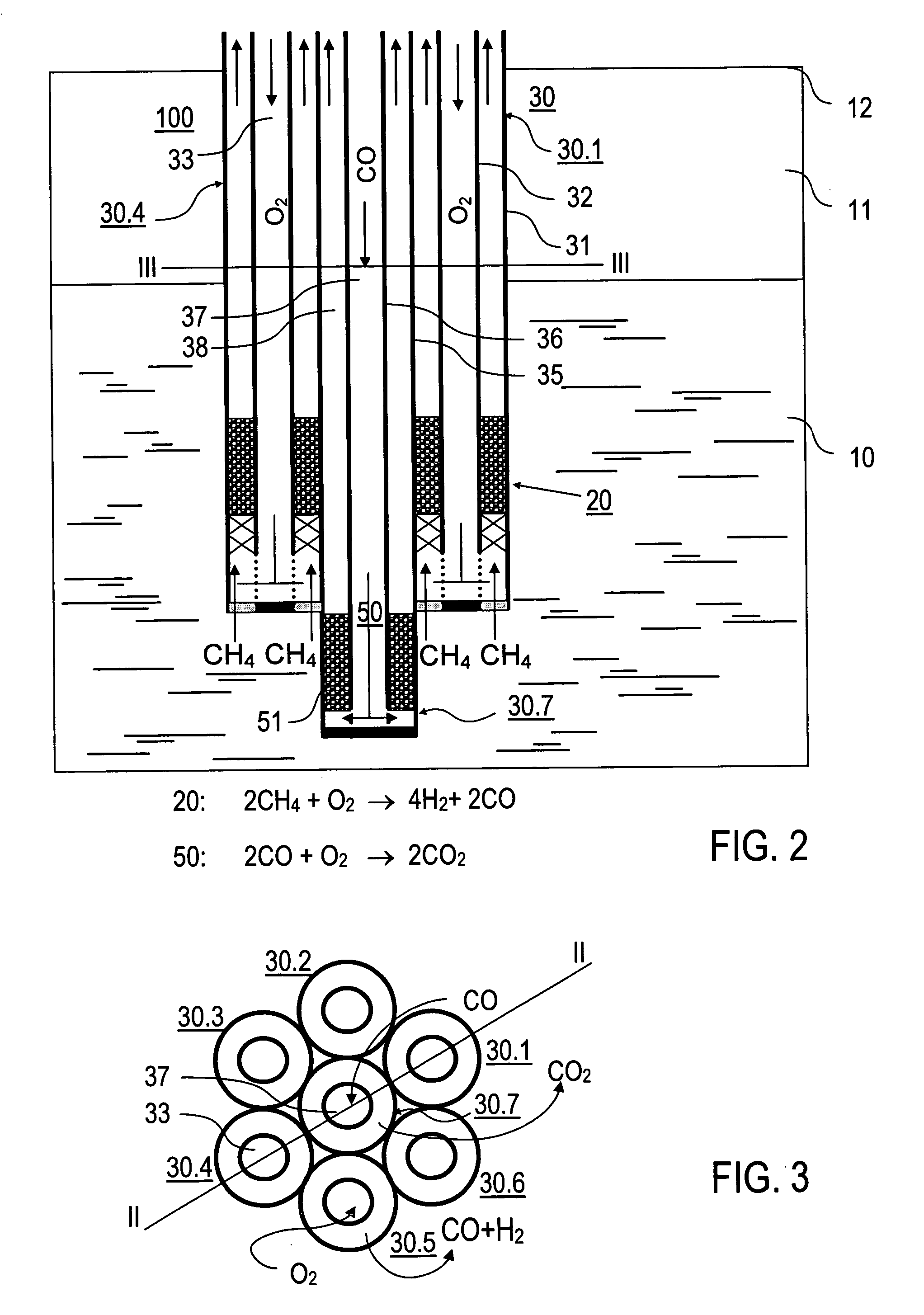
[0025] Another important advantage of the invention is that the gas hydrate heating can be carried out by reaction heat with the available technology for access to natural gas hydrate form ations. The reactor can be arranged with a piping arrangement in a borehole, particularly in a borehole in the gas hydrate formation at the desired depth of a sediment layer with gas hydrates.

Problems solved by technology

However, these processes have proven to be ineffective and energy-intensive.
Sediment layers with gas hydrates have a low permeability, so that the introduction of hot media is only possible with a high expenditure of energy.
However, this chemical treatment of gas hydrates is limited to local effects in the vicinity of a borehole and is furthermore characterized by an unfavorable energy balance.
In addition, laboratory experiments show that an exchange of hydrate-bound methane with CO2 takes place only proportionately and therefore the complete methane gas cannot be extracted from the hydrates.
In the first place, the course of the process is technically very complicated and energetically ineffective.
Another disadvantage consists in a limitation to a narrow extraction plane on which a heating procedure can be carried out.
Thus, a systematic extraction of gas hydrates in a geological formation is only possible with a high expenditure of time and energy.
Furthermore, the conventional release of gases from gas hydrate formations is associated with the following problems.
Moreover, there can be a danger of a destabilization of geological formations resulting in significant risks to the environment, particularly in the case of the extraction of gas hydrates on continental shelves.

Method used


Image

  • Process and device for the thermal stimulation of gas hydrate formations
  • Process and device for the thermal stimulation of gas hydrate formations
  • Process and device for the thermal stimulation of gas hydrate formations

Examples


Embodiment Construction

[0045] The invention is described by way of example in the following with reference made to its use in a borehole. However, the implementation of the invention is not limited to the embodiment explained but is also possible in other geological applications permitting access to gas hydrate formations. Moreover, it is stressed that the attached drawings schematically illustrate the features of the embodiments shown. In the concrete implementation of the invention into practice the concrete dimensional conditions and forms, particularly of the reaction chambers and of the other components can be selected as a function of the use. The device in accordance with the invention is preferably arranged in a known bore pipe that is not shown in the drawings. Details of the borehole and of the boring technology, which are also known, are not described in the following.

[0046] The device 100 according to the invention for the thermal stimulation of gas hydrates is introduced in accordance with F...


PUM

PropertyMeasurementUnit
Pressureaaaaaaaaaa
Metallic bondaaaaaaaaaa
Distanceaaaaaaaaaa

Abstract

A method for the thermal stimulation of a geological gas hydrate formation (10) is described in which thermal energy is supplied to the gas hydrate formation (10) so that gas hydrates in the gas hydrate formation (10) are converted and gaseous components are released and the supplied thermal energy is delivered by an exothermal chemical reaction that takes place in a reactor (20) arranged in the gas hydrate formation (10). A device for carrying out the process is also described.

Description

[0001] The present application claims priority under 35 U.S.C. §119(a) to German Patent Application number DE102004048692.1, which was filed on Oct. 6, 2004, the contents of which is hereby incorporated by reference in its entirety. FIELD OF THE INVENTION [0002] The present invention is related to a process for the thermal stimulation of gas hydrate formations in which gas hydrates are converted under the action of thermal energy, to a device for carrying out the process and to applications of the process. BACKGROUND OF THE INVENTION [0003] Gas hydrate formations (clathrate formations) are terrestrial or marine formations containing gas hydrates. Gas hydrates are solids formed from gases (e.g., methane) and water under certain conditions of pressure and temperature. At low temperatures and high pressures the gases are enclosed in clathrate cages formed by water molecules. These conditions occur, e.g., in marine sediments in the ocean and in sediments of permafrost regions. There is ...

Claims


Application Information

Patent Timeline
IPC IPC(8): B01D53/14E21B43/00E21B43/24E21B43/247
CPCE21B36/008E21B43/295
Inventor SCHICKS, JUDITH MARIA
Owner GEOFORSCHUNGSZENT POTSDAM A CORP OF GERMANY
Learn More